Wood Moulding And Proportions

When recreating a period set from the 1800’s in particular, it’s difficult to really replicate the designs of the period because current wood moulding and millwork don’t allow for what was a common practice by designers and architects; true proportional design.

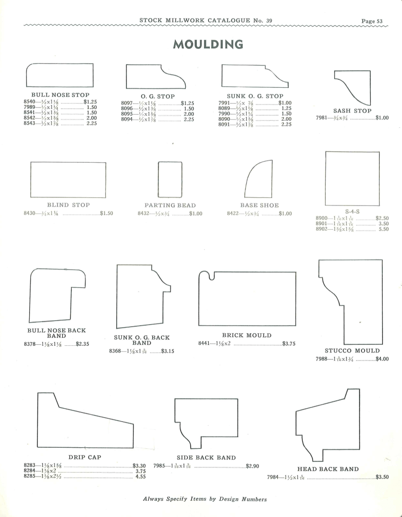
A moulding catalogue of today looks very different from the original moulding catalogues of the 1800’s. Not only because they contained a larger variety of profiles, but there was a large selection of different sizes for almost every profile that they offered.

The cover of the 1874 Universal Moulding Book. One of the first millwork catalogues for wood moulding.

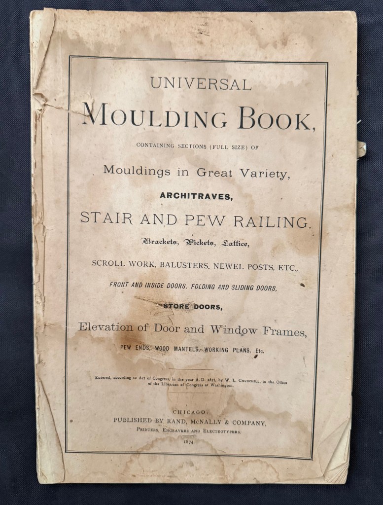
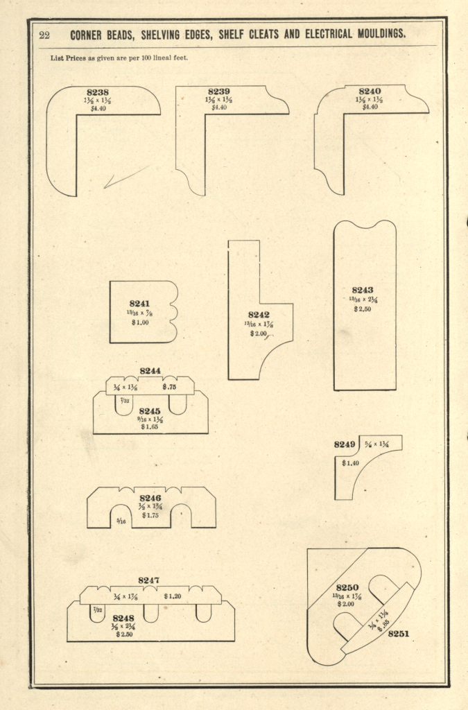
The oldest moulding catalogue that I own is the Universal Moulding Book from 1874. This catalogue shows over 650 moulding profiles in full size. It isn’t the first version. I know this because the catalogue states that 46 profiles have been phased out from a previous catalogue.

Here is a page of a profile known as a Quirked Greek Ogee and Bevel, a popular profile in the mid 19th century. Notice that there are 17 different sizes.
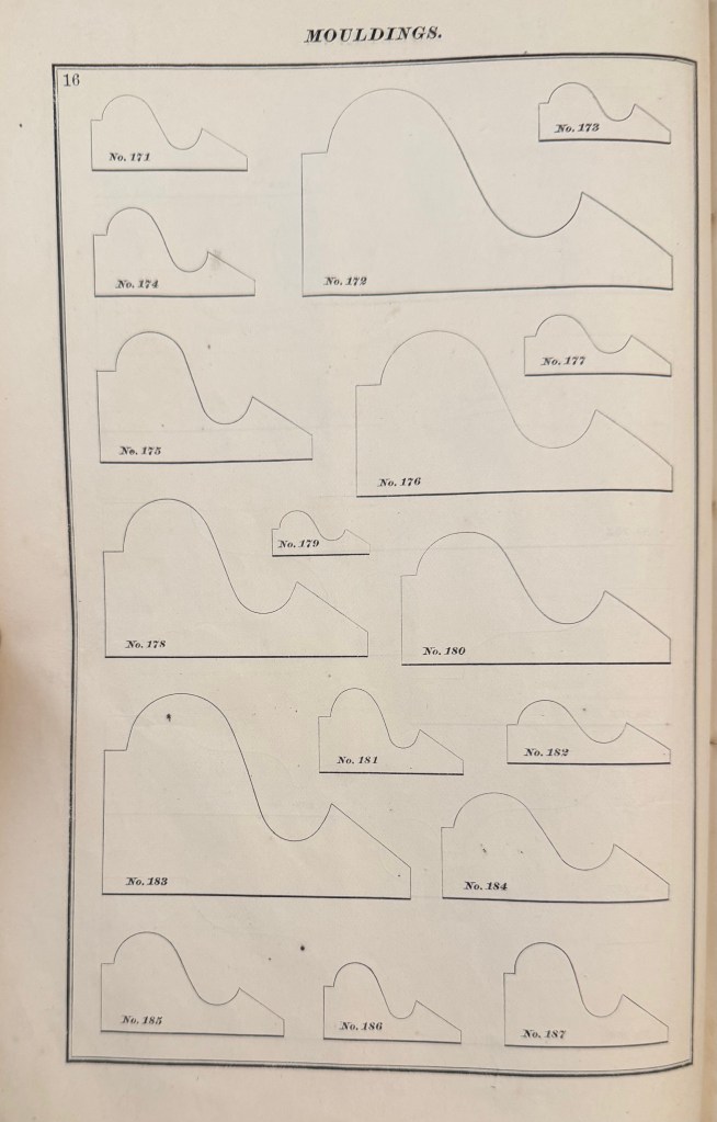
Why so many sizes?

Originally moulding or architectural enrichment wasn’t an afterthought. The mouldings were designed to be used in proportion to the openings that they surrounded.

In America, and England, before the Industrial Revolution, wood mouldings were made by hand. (plaster ornament was as well). With a set of planes called Hollows and Rounds, an infinite variety of moulding profiles could be created. A set of planes were designed to created 1/6th diameter arcs in increments of 1/16th inch.

My working set of hollows and rounds

Various pattern books of the period laid out the formulas for creating the mouldings according to the width of the openings. In his 1827 version of Builder’s Companion, Asher Benjamin wrote that for a door or window, the proper proportion would be found by dividing the opening into eight parts and giving one to the width of the moulding, He noted that this formula would provide a different width for different widths of doors and windows, but said that it wasn’t good to have different widths of architraves in the same room.

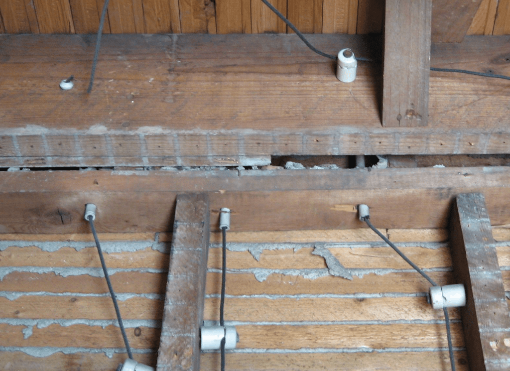
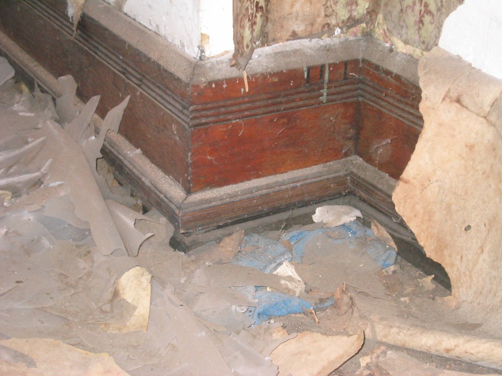
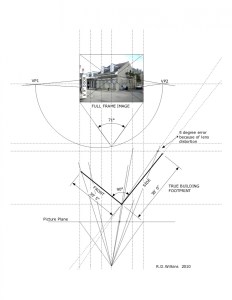
Obviously he wasn’t around to comment on this house interior……….

1839 New Orleans 4-bay townhouse

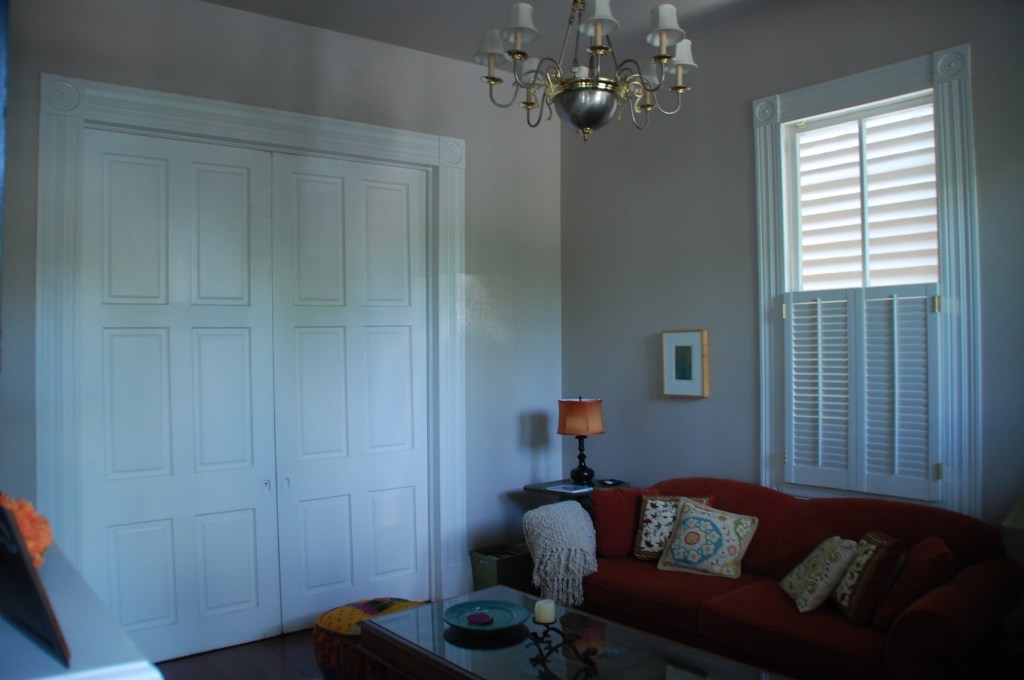
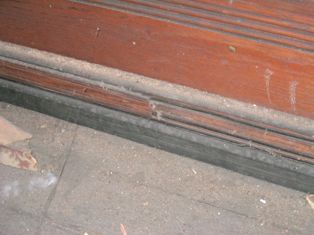
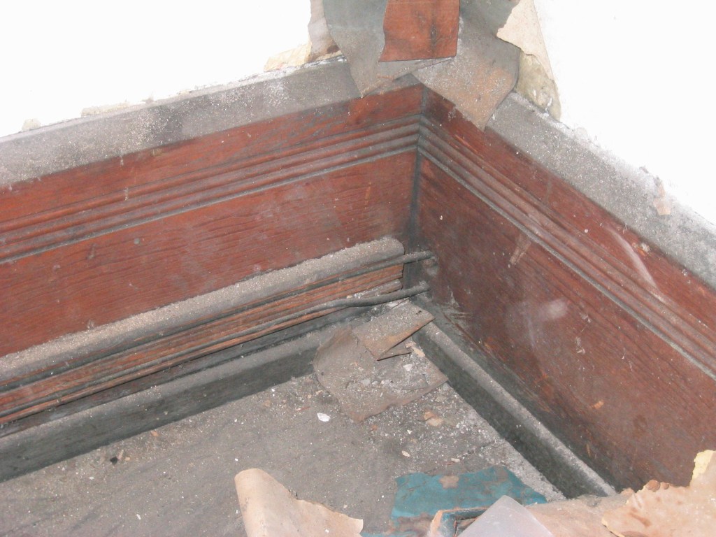
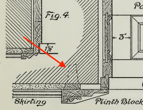
The pocket door opening in the photo is 6′ wide while the window width is about 3′ wide. You probably don’t notice that the architraves and the corner blocks are different sizes. The casing aound the doos is about 6″ in width while the window casing is less than 5″. The casing that frames the doors would look too large around the windows while the window casing width would be too diminished by the pocket door opening width.

Because the casing widths conform to the opening sizes, they look similar enough in size for their differences to be hard to recognize. The fact that they have proportional details within the overal common profile helps as well.

When the factory-made millworker begain to replace the on-site handmade moulding, they settled on a series of profile sizes that would fit most situations based on common door and window opening sizes.

This variety of sizes began to diminish into the 20th century until around 1940, when most catalogues began to offer only a few or even just one size of each profile.

A page from the 1939 Stock Millwork Catalogue

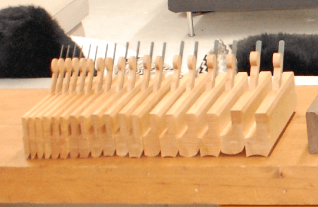
When you have a design that requires moulding profiles that aren’t available, (which is a common problem with 19th century Victorian designs), and you aren’t able to create a built-up moulding from available profiles, you may have to have a set of custom knifes made.

If you order enough linear feet of the mould, some shops will waive the knife fee as it adds to their selection of profiles. Be sure you look into custom knifes before you discount it as being too expensive. The job is also done by CNC now rather than hand-grinding. so the actual operation is not a bid deal.

Moulding In The Classical Tradition Lecture – February 26

If you are in the Los Angeles area at the end of February, The Southern California chapter of the ICAA (Institute of Classical Architecture and Art) is presenting a lecture entitled “Authenticity & Historic Design in Architectural Millwork” on February 26, from 6:00 to 8:00 PM.

The presenter will be Brent Hull, a nationally recognized expert on historic design and architectural authenticity. He will present information and inspiration from his new book “The Design and Manufacturing of Historic Millwork From 1740-1950” published by Wiley & Sons. 2025.

Hull is an award-winning master builder and expert in historically accurate architectural millwork and mouldings. For over thirty years his craftsmanship has enhanced nationally registered properties and homes across the country. Hull honed his expertise at Boston’s North Bennet Street School where he trained in the art of traditional building and historic preservation prior to founding Hull Millwork & Hull Homes in Fort Worth, Texas.

He has authored five books on historic millwork and architectural design including his most recent work, which is a follow-up to his previous book, “Historic Millwork”, published in 2003. His current book includes moulding of the mid-18th century and early 19th century periods, which weren’t covered in the earlier volume.

He will be talking about the stylistic and functional shifts that accompanied the transition from pre-industrial hand-crafted techniques to mechanized production. Hull provides a framework for identifying period-specific profiles and understanding the design logic that shaped moulding development across two centuries of American building tradition. Participants will gain practical knowledge for making informed specification decisions for restoration and classical new build projects.

Here is the link to register:

https://www.classicist.org/calendar/events/authenticity-and-historic-design-in-architectural-millwork-with-brent-hull

If you aren’t familiar with the ICAA, they are a great resource for connecting with architects and artists who are interested in and trained in the classical arts tradition, both in restoration work and new construction that honors the early periods. They have active chapters all over the country.

Brent will be giving his presentation iat several other chapters around the country so you might check the ICAA calendar if you don’t live on the west coast.

Here is the link to the main ICAA page to find out more about the organization and learn about events in other parts of the country:

https://www.classicist.org


Arch-Anatomy – Electrical Wood Moulding

This is the second in a series of articles on the anatomy of architecture which focuses on construction details. Many of them are details that are now obsolete because of modern building methods or the evolution of designs due to changing tastes.

There is a type of moulding available today called ‘electrical molding’ which is either a formed sheet metal channel or plastic channel that is designed to hide electrical wiring on the inside surface of a wall. This simplifies electrifying a room when new outlets are needed or a new light fixture needs to be installed without cutting into a finished wall surface.

In the late 1800’s the electrification of offices and homes was becoming more popular and the current method of wiring buildings posed a problem. The method at the time was known as ‘knob and tube’. Copper wires which were covered with a rubberized fabric were strung along the unfinished side of walls, underneath floors, or on attic joists and held off the wood surface by attaching them to a line of ceramic knobs which were nailed to the wood studs. When the wiring had to pass through a stud or joist, a hole was drilled and the hole was filled with a ceramic tube for the wires to pass through.

Knob and tube wiring – photo-Laura Scudder
Diagram of typical wiring showing rubberized cloth covering

The problem came when the wiring had to run inside a room interior. A cosmetic solution had to be created to hide electrical, telephone, and telegraph lines from view.

A wooden cleat to be used instead of ceramic knobs.

Cutting into the three-coat plaster and wood lath walls of the period to bury wiring inside them wasn’t an easy option when electrifying previously built houses. Early builders manuals suggested designs that hid the wiring inside moulding on the walls. Some suggested creating a moulding which hid the wiring at the top of a tall wainscot paneled wall, or to create a wide picture rail to serve the purpose.

An example of electrical moulding disguised as a wide picture rail.
Another example of a suggested electrical moulding capped by a picture rail mould.

Electrical moulding doesn’t show up in a lot of the moulding catalogues from the period, but a number of them are represented in the Official Moulding Book in their 1907 to 1913 editions.

No. 8249 and 8251 were meant for either a type of cornice mould or to use to run wiring vertically at a room corner.

The three photos below are photographs I took inside an 1890 office building before it was renovated. I haven’t been ablr to find this exact mould in any catalogue yet but they are a slightly more decorative version of No. 8244 in the Official Moulding Book.

Photo – R. Wilkins
Photo – R. Wilkins
Photo – R. Wilkins

Note that the wiring runs to the next room through holes in the wall which do not have any insulators. This lack of insulators, the fragile nature of the rubberized fabric coating, and the fact that the wiring was not grounded made for serious fire hazards with the early wiring systems.

Sources:

Official Moulding Book – 1907, The Chicago Millwork and Moulding Co, Chicago, IL

Building Construction and Superitendence, F.E. Kidder, Part II, 1911, William Comstock Co. NY

Cassell’s Carpentry And Joinery, Paul Hasluck, 1908, David McKay Publisher, Phila, PA

Arch-Anatomy – Wood Bricks

This is the first of a series of articles on the anatomy of architecture which focuses on construction details. Many of them are details that are now obsolete because of modern building methods or the evolution of designs due to changing tastes.

(An expanded explanation of an obscure but interesting entry in the Wrand Film Design Glossary.)

If you try to search for ‘wood bricks’ on the internet, you’ll probably come up with some strange answers. They were a standard feature of brick construction in the nineteeth century that went out of fashion for a number of reasons.

With masonry building construction there has always been the problem of attaching wood elements to stone or brick structures. This was often accomplished by inserting wood plugs into the wall surfaces as an attachment point for nails, or by driving nails into the mortar of joints.

A wood plug in a stone wall of a 17th century Paris hotel.
From a 19th century builders manual showing the use of wood plugs for attaching a door frame.
Wooden plugs in early 20th century brick.

The use of ‘wood bricks’ most likely evolved in England before spreading to America. Most building manuals of the period that mention their use suggest using well-seasoned hardwood billets set between the brick courses at intervals for a way of attaching the wood linings for doorways and window framing.

For narrower wall opening, this lining could consist of a single board like in the illustration below.

Use of a single plank as a door frame lining for a brick wall. Note that the wood bricks are also used to attach the grounds at the door frame for plasterwork. The architrave exhibits typical Neo-colonial profiles, while the bolection mould on the doors frame is a mould typical of Greek Revival houses, a quirked Greek ogee and bevel combined with a fillet and cove, topped with an astragal, fillet, and cove.

For larger openings in thicker walls, the wood bricks were made longer and the linings were made of several pieces of sawn and planed boards, assembled in what was called a skeleton framed jamb.

The skeleton frame is attached to the wood bricks as well as the wood lintel.

Early manuals show this framework to be mortised and tenoned similar to a frame for furniture, but some mid-ninteeth century examples in America have been observed to be simple vertical boards nailed to the wood bricks rather than a M&T frame. This method would have definitely cut down on the construction time.

The image on the left shows the wood bricks in place while the image on the right shows the vertical boards nailed to them to act as the arch frame lining. Notice the archway lining at the top with boards that have been kerfed at regular intervals to allow the wood to form to the brick archway without having to steam bend them.

Some turn-of-the-century buildings display a more haphazard approach to wood bricks where framing cut offs of softwood were used instead of hardwood, as in the photos below.

Softwood framing cut-offs used in place of hardwood.
From an early 20th century building in Southern California. Wood bricks are set at 4′ from the floor. Most likely for a wanescot and chair rail.
Long strips of wood inserted in the brick for attaching a paneled wall detail in a 1870’s rural school house.
Two more examples of what appears to be framing lumber used as wood bricks.
Pieces of what seems to be lath for plaster inserted into the mortar joints between bricks as an attachment point.
An unusual sight I found on a building in the Mid-west. The exterior brick wall has eroded to the point that the wood bricks of a door frame have been exposed to the outside.

What Is A “Double Dap” Hinge?

One of the reasons that I wrote the Wrand Film Glossary was to record many of the obscure film and entertainment industry terms that get passes down orally but are never recorded.

Art department and set construction lingo is usually not included in the typical film glossary, and “Double dap” is one of those odd terms that you will hear used by Prop Makers* but have probably never had it explained.

The term refers to how the hinges of a door on a stage set are to be installed. Normally the installation of hinges for a door involves creating mortises in the door stile and the jamb that match the thickness of the hinge leaves. That’s referred to as a “single dap” installation. (Note: this is specifically for doors in North America or the UK. Many Continental European doors are half-overlay and don’t use the type of leaf hinges that are standard here.)

Typical hinge installation – referred to as a Single Dap

A “double dap” installation involves creating a mortise in the door which is twice as deep as usual and not making a mortise in the jamb, as shown below.

Example of a Double Dapped hinge

The diagram below is a side-by-side plan view showing both types of installation.

So what’s the purpose of this? Well, this is something that is more typical on sets for a broadcast show than on sets for a feature film.

One advantage is speed. We tend to build sets at a pretty brisk pace, sometimes building an entire set over a weekend. For example, if you have a set with six doors, that means you need to install 18 hinges, which means routing 32 mortises. With a double dap installation you cut that number in half.

Another advantage is if you are redressing a set and need to change out the door of an opening for a different door. With a standard installation, you will need to patch and fill and re-rout three mortises. Instead you just need to fill some screw holes.

This is also the case if you need to change the swing direction of a door at the last moment. (Good luck prying off and repositioning that door stop.)

Double dapping has fallen out of favor lately. Production Designers don’t like the look of it for one thing. (Along with Phillips head screws on a period hinge!) They tend to stick out particularly when the hinges are a contrasting color from the jamb or if the wood is painted a light color and the hinges have a dark laquer/black finish. In some instances this condition can either visually hide the extra mortise depth or accentuate it.

Also, notice the round corners on the hinges in the photos. Round corner hinges are a 20th century invention to speed up production. Once machinery, i.e. routers, was being used for mortising, it became a lot faster to create hinges with leaves that didn’t require squaring off the mortise corners as was necessary for period, square hinges. Round corner hinges come in 1/4″ and 5/8″ radius corners, so be aware of what radius size they are if you’re choosing hinges for a door that has already been mortised.

Note: Prop Maker is a designation for a union stage carpenter in Los Angeles to differentiate them from a ‘civilian’ carpenter. They are trained it building theatrical scenery of all types and historical periods and specialize in creating scenery for film productions. They are more similar to cabinet makers than a typical carpenter and are skilled in construction techniques and methods that would baffle most people outside the entertainment industry.

The Digital Bookshelf – “Plastering Plain And Decorative”

My preference for books is always a hard copy, but sometimes having easy access to the information is more important than having a physical book, especially when copies of the actual book are impossible to find or really expensive.

That’s the case with this book, Plastering Plain and Decorative. First published in 1890, the book has become known as “The Plasterer’s Bible”. Now out of print, except for the occasional third-party reprint, it went through four editions. It contains hundreds of black & white photographs and drawings which aren’t always of a very good quality with most of the modern reprints, usually because they are printed in a smaller size than the original quarto size and because the scan quality of the original images is bad.

On top of not being of a very good quality, they are also nearly as expensive as an original copy, which would be a better bet as those are stitched like a traditional book and not perfect-bound (glued edges) like all soft cover books are. I have seen so-so quality reprints go from anywhere from $100 to $300.

Fortunately there is an inexpensive (free) copy of the book online at the Internet Archive. This isn’t just a book of nice drawings and photos, this is a book written for crafts people. Besides the layout diagrams, there are drawings of the actual tools used to create complicated plaster elements and a huge list of plaster types as well as the ingredients and mixtures used to create them in various time periods, such as instructions on what type of animal hair to use in the staff pieces for strength. It is an early edition of the book and contains over 700 pages which is more than is included in later editions.

The book covers not just typical plasterwork but, sculpting, mold making, terra cotta work, scagliola, sgraffito, and composite decorations. Besides Western European techniques it examines designs and techniques from Japan, China, India, Persia and the Middle East.

There is also a section on concrete work such as staircases, sidewalks, road, roofs, fountains, and other decorative elements.

You can find the digital book here at The Internet Archive. There are a number of different digital files available for download with varying file sizes depending on the quality of the images you want to have available.

New 10-Week Set Design Fundamentals Course – 50% Off

One-Time Pre-Sale Offer

Wrand Productions announces it’s 10-Week Set Design Fundamentals Course at a Pre-Sale price of 50% off the regular price. This is the only time the series will be offered at this price and it will return to the normal price when the series begins on October 31.

This self-paced online series covers the fundamental skills that a Set Designer in the feature film and television industry here in Los Angeles are expected to have.

This is similar in difficulty to a one-semester graduate-level program at a university, but much of the material presented here is not covered at most colleges and is normally only available at the professional level. I’ve been developing this series for several years, basing it on classes I teach at the Art Directors Guild in Los Angeles.

Here is an outline of the material that will be covered in the series:

Week 1 – The Basics

Standard drafting conventions and symbols for set construction drawings. Set construction: typical flat construction techniques and variations.

Week 2 – Cameras & Optics

Understanding basic camera and lens terms: aspect ratios, focal length, depth of field, sensor sizes, exposure, stage lighting, using camera angle templates.

Scaling from photographs and artwork: calculating dimensions, understanding picture perspective and allowing for lens distortion.

Week 3 – Analyzing the Script / Reference Materials

How to break down a script for set design; using storyboards; techniques for estimating drawing time schedules.

References: using online, printed, and survey photo references; building a reference library on a budget.

Week 4 – Working Drawings

Step-by-step directions on creating proper construction drawings: plans and elevations; details, full-size details, and digital cut files; reflected ceilings and furniture plans; stage spotting plans, and director’s plans.

Week 5 – Door & Window Details

Diagrams and explanations of door and window construction and various adaptations for stage sets; creating accurate-looking period reconstructions; understanding, using, and sourcing hardware.

Week 6 – Stairways

The fundamentals of stair design: types of stairs, stair construction, how the choice of stair type affects design, and designing elliptical stairs.

Week 7 – Mouldings & Staff Elements

Understanding and using the Classical Orders of architecture; the proportions of mouldings based on style type; using a moulding catalog and creating built-up moulds.

Using plaster staff and compo elements in a set; designing with brick skins and textured surfaces.

Week 8 – Backings, Special Effects, & Visual Effects

Using painted and photo backings: The advantages and drawbacks of various types; creating custom backings; how to calculate correct placement distance from the set.

Special effects considerations: replicating fire, water, and wind effects; understanding legal requirements for special effects work on a sound stage; dealing with practical fireplaces.

Visual effects work: shooting with green or blue screens; using LED walls or volumes.

Week 9 – Backlots & Location Surveys

Shooting on studio backlots; shooting on location; proper surveying techniques; assembling a personal survey tool kit.

Week 10 – Physical Models

The advantages of physical study models; determining model scales; various model types and construction techniques.

Class Materials & Videos

Each week there will be tools, charts, and reference material to download as well as video instruction to help you do the exercises and create your portfolio drawings.

Along with the classes, you’ll have access to a private chat area that is only available to students of the series and alumnae who have taken courses previously. Here you’ll be able to meet other designers, discuss class material, get advice on your career, and exchange ideas and experiences from both the classes and real-world entertainment jobs.

Prerequisites:

– You must know how to draft. Drafting ability is essential to effectively completing the course and ending up with a set of professional quality working drawings. I’ll be offering a course on drafting later in 2022 to fulfill this prerequisite.

– Be familiar with CAD software  –  You are free to use any CAD software you are familiar with. Using software that you are still learning may make the lessons more challenging than you can handle. There is no standard drawing software in the entertainment industry as far as the Art Department is concerned. There are preferences among certain designers but one aspect of the job is a need to create files that can be used by many different other programs. 3D modeling won’t be required for any of the class projects but feel free to work that way if that is part of your usual design process.

There is a 14-day money-back guarantee from the time you begin the series if you change your mind. If you’re unsure about whether the series is right for you, you can schedule a free 15-minute discovery call to talk with me and I’ll be happy to answer any questions you might have.

Sign up for the course and learn more here.

Traditional Skills For A Digital Age

On April 8 and 9, I’ll be teaching two new classes at the Art Director’s Guild in Los Angeles. The classes are free to ADG members.

April 8 – Back Projection and Scaling From Photographs

Prerequisite: none. Class size limit: 12

Tools needed: notebook, calculator (does not have to calculate feet or inches, one on a phone will work fine)

The technique of ‘back projection’ was developed as a way of extracting necessary information from photographs for use with rear projection systems to build set pieces that would match the scale and perspective of the projected ‘plates’.

You’ll learn the basics of this system to find sizes, camera heights, focal lengths of lenses and more.  You’ll learn additional methods of basic photographic scaling that you can use to work from printed images, books or even your computer screen. You’ll leave with a set of tools, including digital calipers, and the knowledge to be able to use this practical and valuable skill.

 April 9 – Architectural Moulding

Prerequisite: none. Class size limit: 20

Tools needed: notebook

Curb your fear of moulding! This class will examine the history and development of architectural moulding in the western architectural tradition and trace their roots from ancient cultures. You’ll learn the 8 basic shapes that make up most profiles, understand the transition from Greek to Roman moulding, learn the proper names of mouldings from their beginnings, and learn the correct use of moulding profiles by architectural period and style.

You’ll learn what’s wrong with your moulding catalogue and also get a list of moulding catalogue profiles by date so you can classify them by their period.

And,  I’ll be bringing in many of my 18th and 19th century British, American and French moulding planes and you’ll see a demonstration of ‘sticking’, or creating traditional wood mouldings by hand.

The Digital Bookshelf – Furniture Mouldings

“There is a tendency among those accustomed to the large-scale of moulding detail on exterior work in wood or stone to make their mouldings on furniture and interior woodwork too large. The full-size furniture moulding so carefully drawn by Mr. Warne should be of the utmost service not only to furniture designers but to students of architecture and interior decoration.”

plate 21_warne


plate 4_warne


“This book covers many different types of English furniture; bedsteads, bookcases, bureaus, cabinets, chests, cupboards, chairs and others. This book illustrates cover this book covers molding details on English furniture from about 1574 to 1820 molding is the method adopted by the cabinetmaker to give definition to the lines of his work and the sections of molded detail very very much as one style has succeeded another through the oak, walnut, mahogany and satinwood periods of English furniture the workings of moldings was then so laborious that the craftsman use them with greater restraint and obtained more pleasing effects by their use than is frequently the case today when profusion often eliminates interest.”

H. P. Shapland, 1923


E.j. Warne’s book, Furniture Mouldings, is still one of the best resources on 16th to 19th century British furniture. Almost never out of print, copies can be had for as little as $1.

Until you get a print copy, you can download a digital scan of the book below. Scanned from an ex library copy, there are a number of damaged pages but you can get a good idea of the scope of the book.

FurnitureMoulding_EJWarne_1923


– R.D. Wilkins


Historical Moulding Catalogues For Download


1938 moulding

Chris Schwarz over at Lost Art Press posted a blog entry yesterday with links to three moulding catalogues you can download. The catalogues range from a 1938 catalogue using the old Universal system where the profile numbers were a fairly universal ( at least within the U.S.) numbering system called the 8000 system. The original numbering system begun in the mid 1800’s used a three digit number starting with 1. You can see how the inventory of stock moulds changed over the years as manufacturers offered fewer and fewer profiles. The mid 1800’s catalogues included over 600 different profiles which would dwindle to less than 50 in many catalogues in the early 1950’s.

Here’s three examples that show the slow loss of the variety of stock stop moulds, the first from the 1890’s catalogue, the second from a 1938 catalogue and the last from a booklet from the 1960’s.


stops from the 1890 Universal catalogue

stops from the 1890 Universal catalogue

Stop profiles from a 1938 catalogue

Stop profiles from a 1938 catalogue

stop profiles from a 1960's catalogue

stop profiles from a 1960’s catalogue

You can read the blog article and download the catalogues at this link. Special thanks to Chris, Eric Brown and Thor Mikesell for sharing the research material.