Why You Need Full Size Details

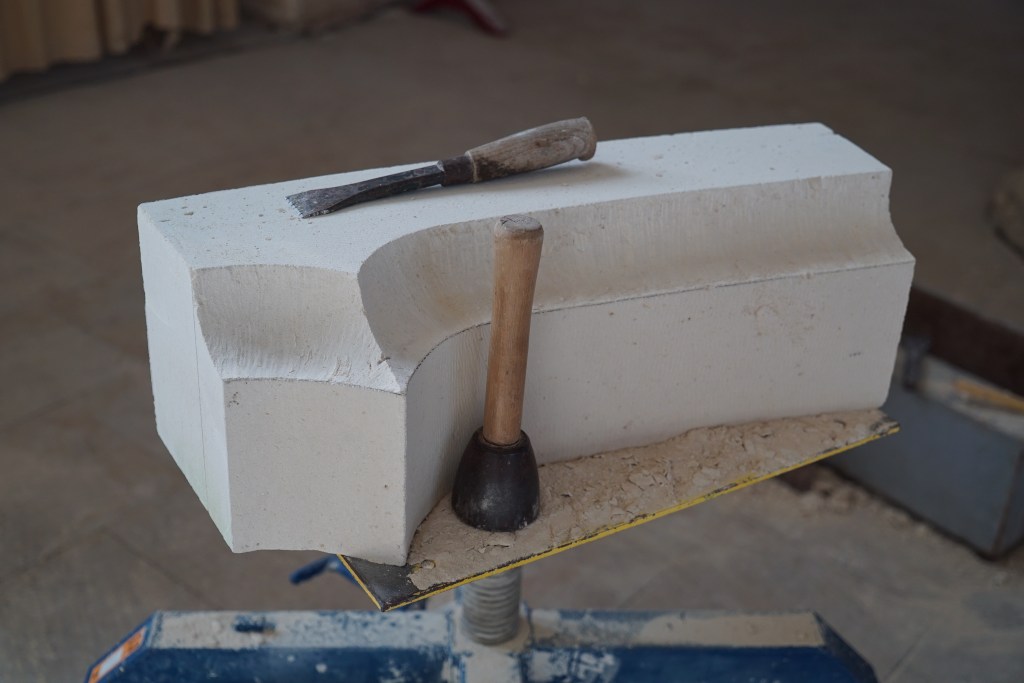
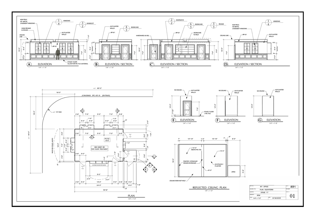
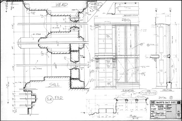
On construction drawings they are noted as an FSD, an abbreviation for Full Size Detail. You need them to visually describe exactly how something is to be built, whether it’s a built-up moulding profile or a complicated mechanical detail.

Here is an example of a typical situation where an FSD is needed. Note the red arrow pointing to a detail bubble that reads, ” FSD – 8A”. This is noting a sub-detail of a window detail labeled as #8.
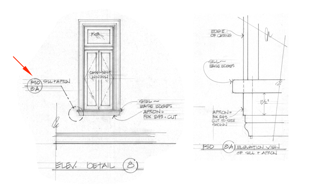
Detail drawing by Dawn Snyder

The detail calls out a window sill apron mould with the moulding profile number and a note that the moulding is “cut”. This means that rather than being used as-is, the moulding needs to be altered in some way. This level of detail is impossible to read on the elevation which is drawn at 3/4″= 1′-0″.

The FSD beside it shows how the moulding is to be placed in relation to the other window parts as well as shows that the plinth of the moulding profile is to be cut down to 1 1/2″. Unless you don’t care how the window ends up looking, you need to include FSD drawings if you have specific details in mind.

Here is another FSD through a window jamb. This drawing shows the jamb thickness, sash thicknesses and widths, the moulding profiles, architrave, and panel moulds. An FSD is needed for this complicated level of period details.
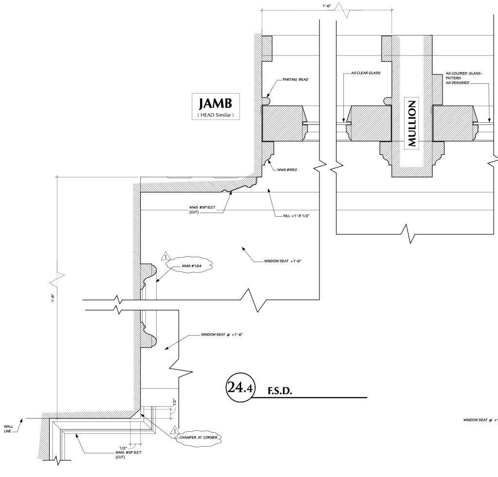
FSD Window detail – R D Wilkins

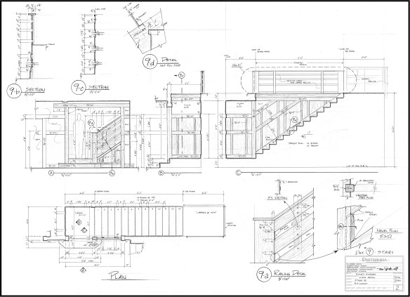
Below is an FSD of a vertical section through a platform riser. Here you can see notes as to materials, fasteners, and electrical lighting effects. Again, it’s impossible to communicate this level of detail in a smaller scale of drawing. You may encounter some situations where you can get by with a half-scale or half full-size drawings, but these aren’t recommended if a full size detail is possible.
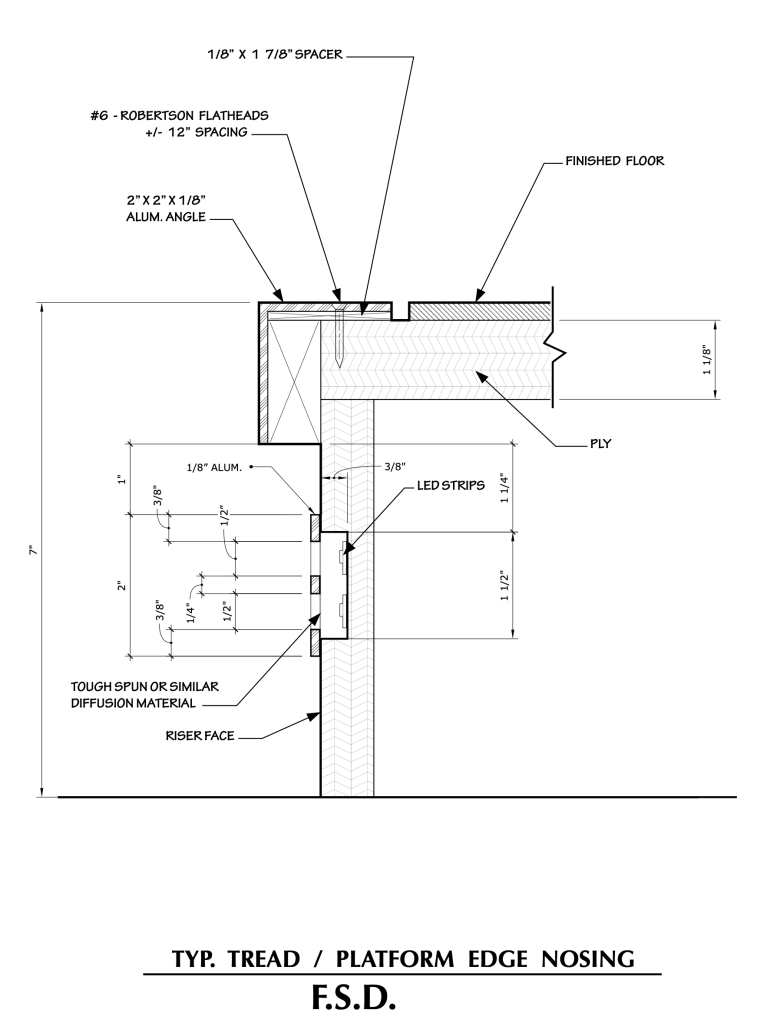
FSD platforn detail – R D Wilkins

A note on dimensioning: You’ll notice that in the section through the window jamb that there are few dimensions. Only the distances where the drawing contains a ‘broken’ wall line are dimensioned. This is traditional, as the prints were originally made as a direct contact print and the set designer was sure that the prop makers could scale from the drawing and get correct measurements. This was the point of a full-size, as you’ll see below.

Once CAD became the standard, and you couldn’t be sure that the print was made at 100%, and people began to work from prints that were smaller than intended, there was more assurance in completely dimensioning even an FSD. This is for the Art Director on a show to make a call on.

Shop Drawings & Story Sticks

There’s nothing new about the concept of full size drawings. It’s a technique that’s thousands of years old.
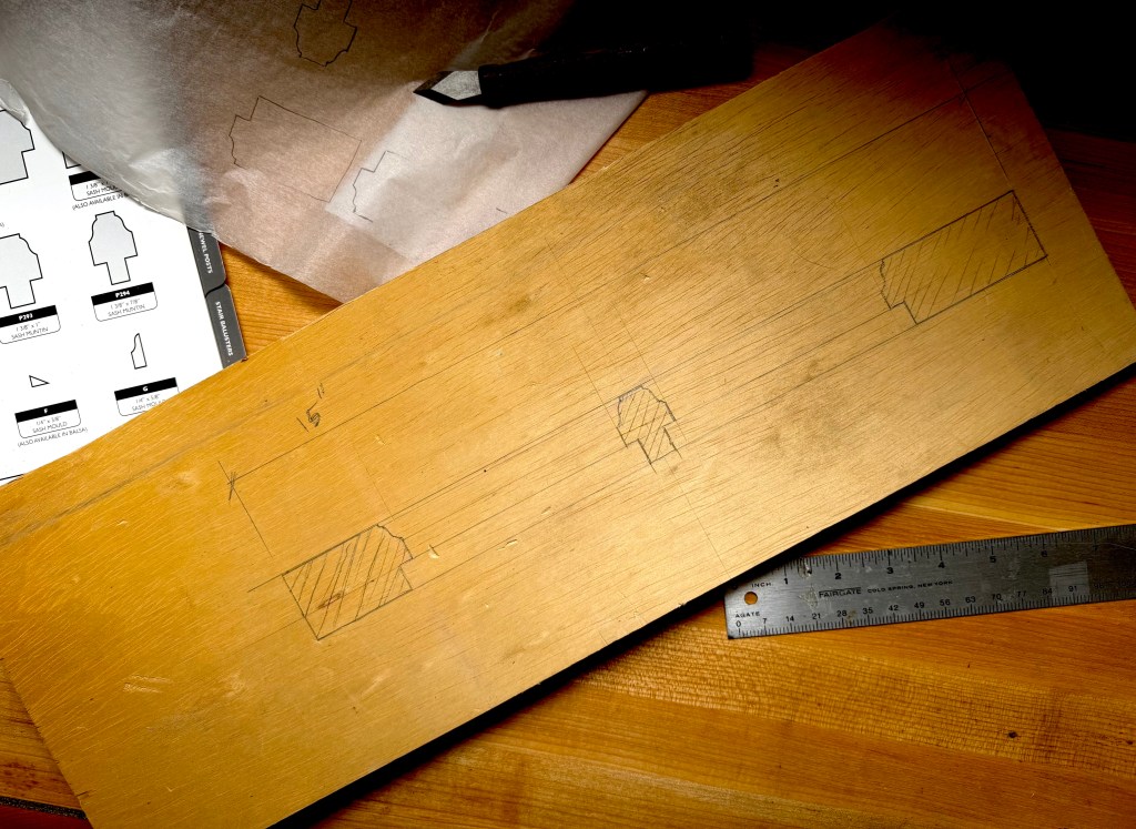
A shop drawing for a small window sash, drawn in pencil on a scrap board.

When I was a prop maker, we were trained to create shop drawings for things like mouldings, windows, and doors. On television shows there is not often time to do full size details of every set element and it often fell to us to create a shop drawing to ensure accuracy when laying out the pieces for a built object, especially a window. Nothing sucks as bad as inserting window sash into a frame and finding out the meeting rails are off by a quarter inch.

In the best case, a full size section has been drawn and you can either pull dimensions off the drawing or glue one to a piece of door skin to cut a template out on a bandsaw.

Traditionally jointers, carpenters, and stone carvers created their own story sticks or setting-out rods to be sure that their cuts were accurate, or full size patterns to check the true size of their work piece.
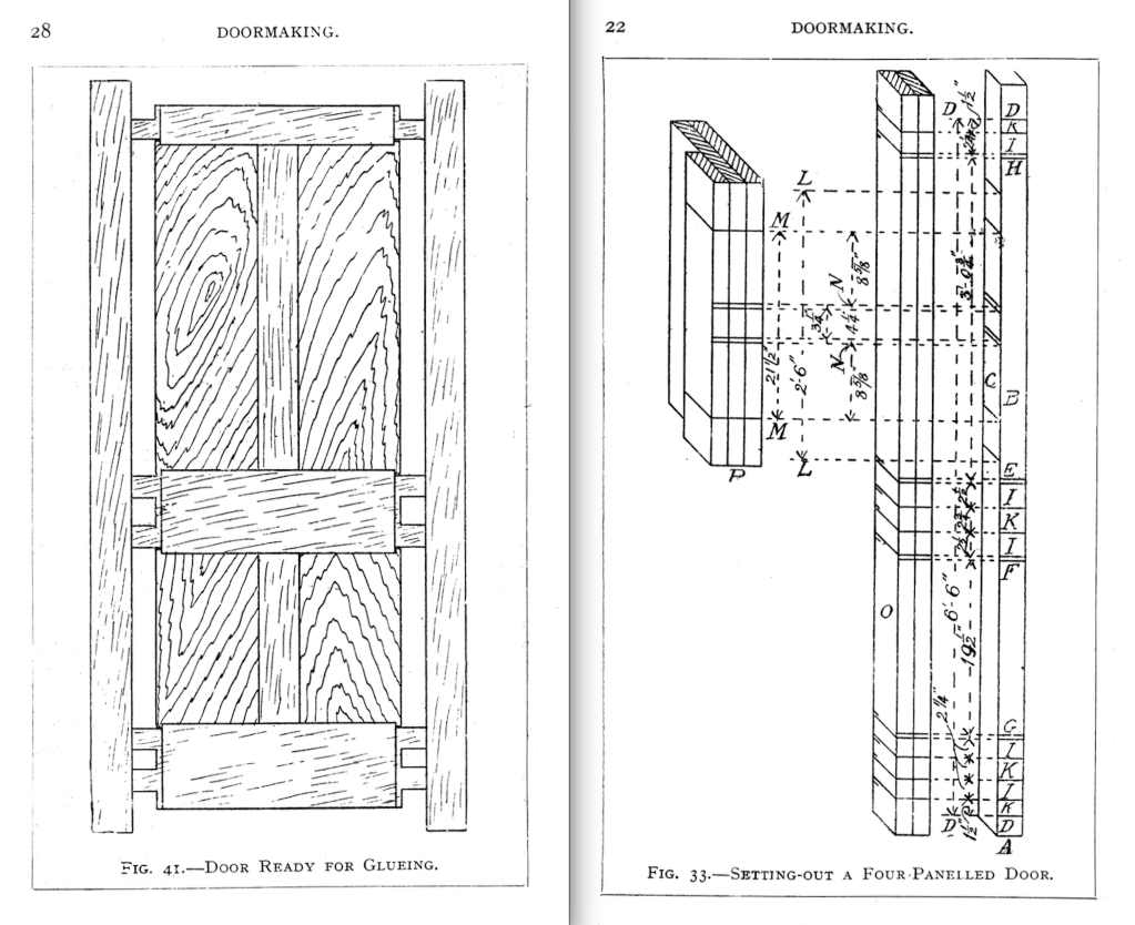
An example of a Setting-out rod for a 4-panel door. This is from a reprint of an excellent little book called Doormaking & Windowmaking from Lost Art Press.

In traditional Japanese house construction, the master carpenter would lay out all the major dimensions for a house on a master story rod called a Kensao. This was like a blueprint on a stick and would be referred to for all questions about construction measurements or additions to the structure. When the house was completed, the rod was kept in the eaves under the roof of the building.
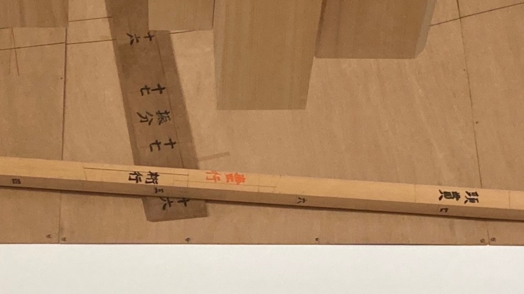
A kensao which was part of the collection of the Masters Of Carpentry exhibit at the Japanese House in Los Angeles.

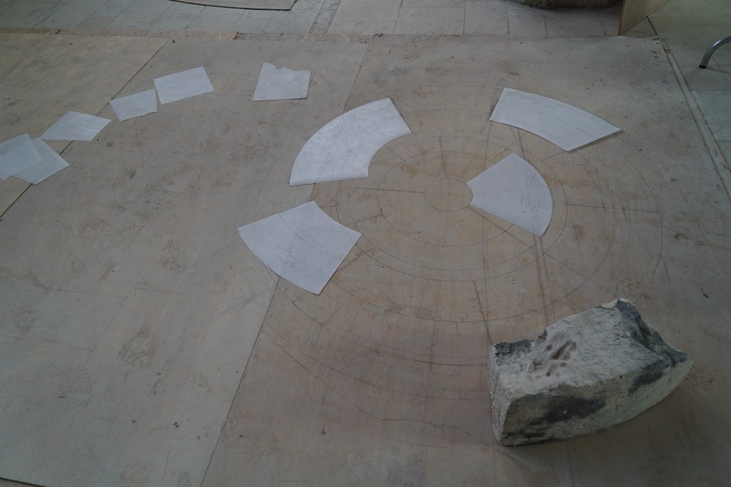
In the Middle Ages and the Gothic period, stone building details were laid out in full size on a tracing floor, a floor that had a smooth layer of plaster applied to it on which the details were laid out with a large compass and straight edges that the stonemasons referred to for each separate element to make sure that they would fit together.
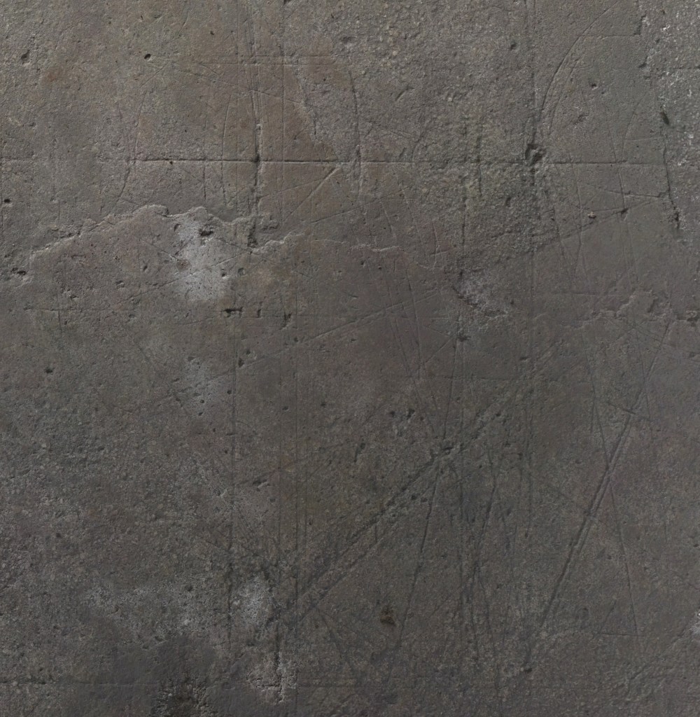
remaining images from a tracing floor

I was able to watch some stonemasons in France repair the windows of a medieval church and saw their modern day version of the original process. The design was drawn out full size on thin plywood sheets. This pattern was transferred to separate patterns on thin plastic which were then used to trace the outline onto the stone itself.
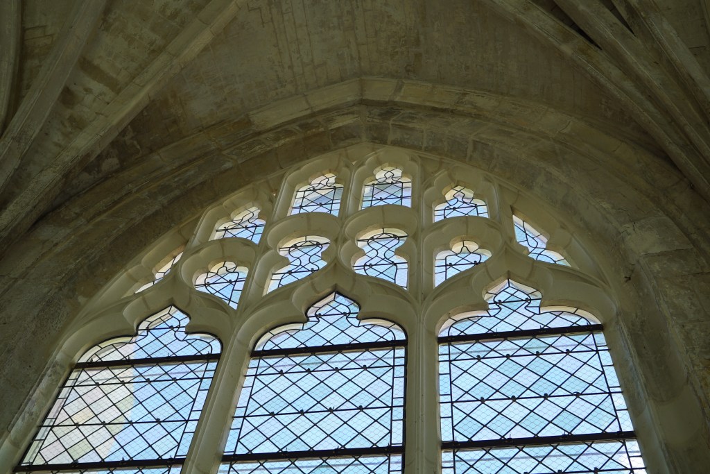
newly replaced tracery
full size detail on plywood with individual stone patterns in plastic
Individual stone tracery section in progress

Production Designer Sarah Knowles recently told me about a new exhibition at The Met in New York City. Entitled Gothic by Design: The Dawn of Architectural Draftsmanship, the show includes over 90 original pieces that span from the 13th to the 16th century. On now though July 19.

Many of these pieces were meant to be presentation artwork to show the sponsor what the final building would look like, but there are several construction drawings in the gallery show.
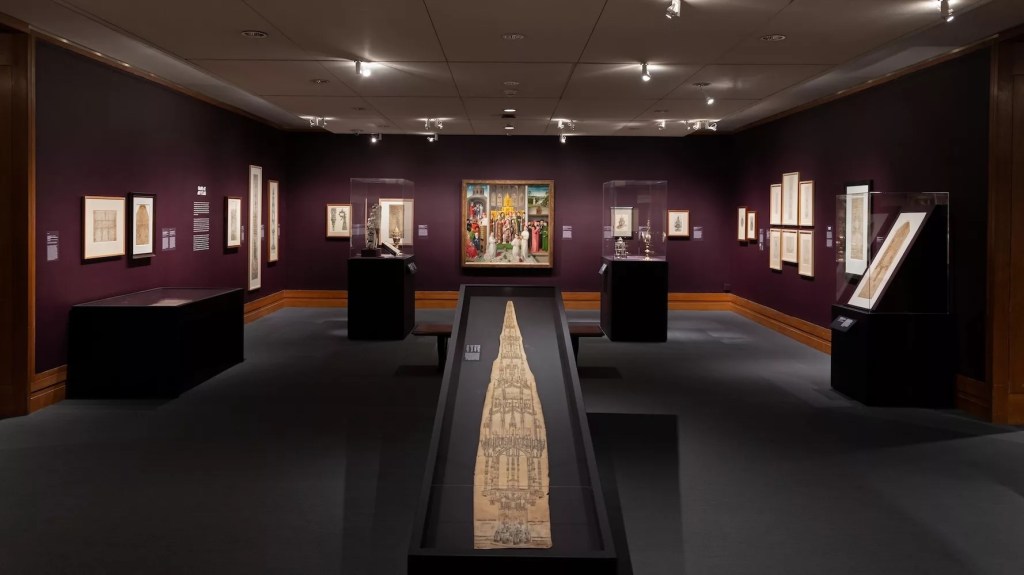
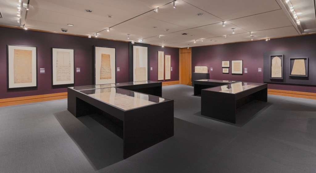
The Met – Gothic By Design Exhibit. Photo: Metropolitan Museum Of Art New York

One of the drawings s a plan and developed stair stringer for the Saint Stephens Cathedral in Vienna. The stairs are shown in a painting by artist Rudolf von Alt in 1841.
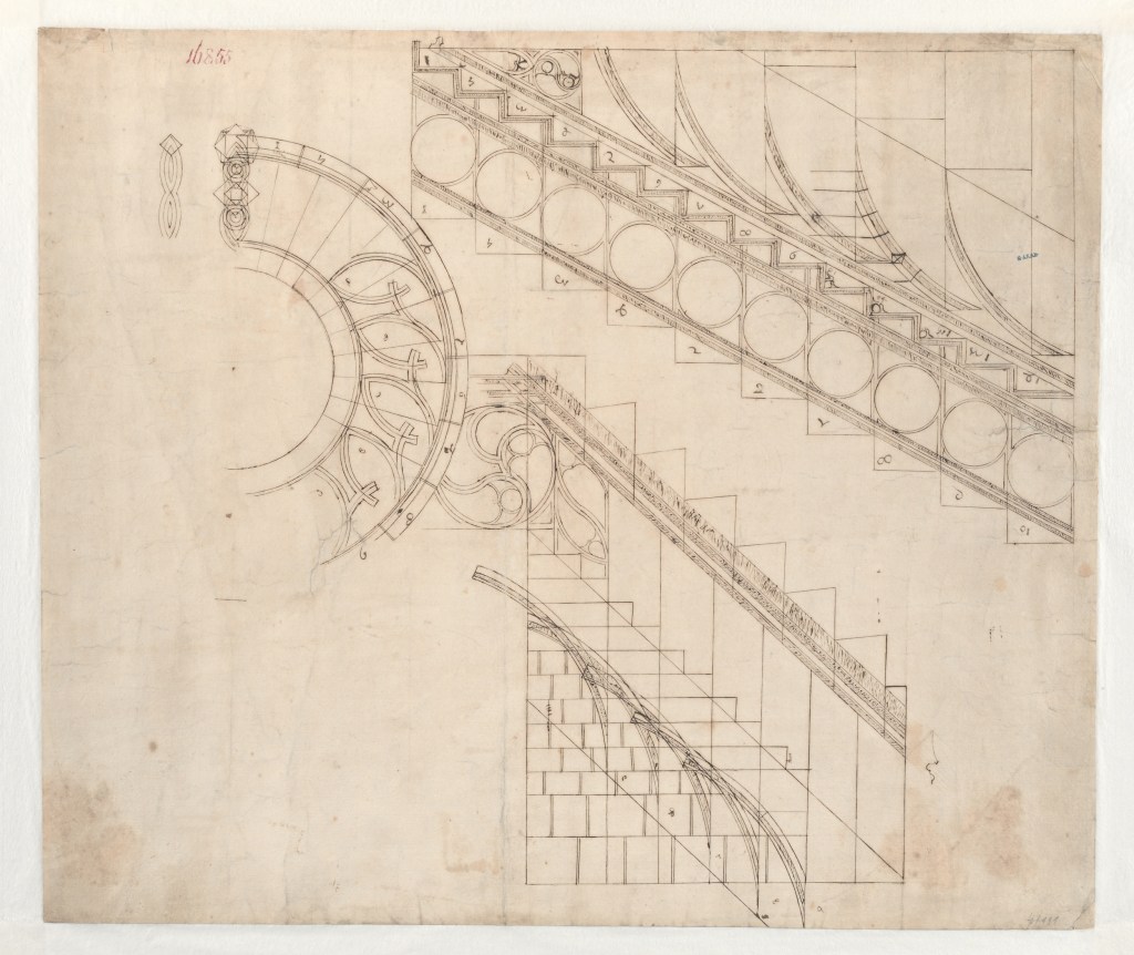
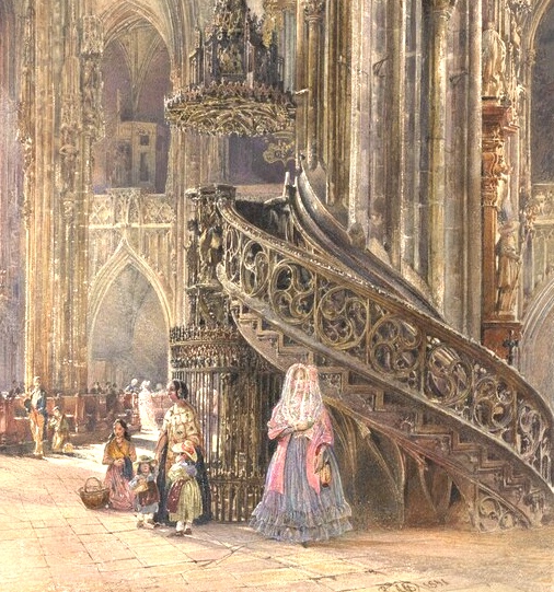
Drawing by Anton Pilgram, 1515. Photo: Metropolitan Museum Of Art, New York
The staircase is shown in a painting by Anton von Alt from 1841

The one full-size detail is of a vaulting detail from the Chapel of Saint Catherine in Vienna.

Similar to the plastic sheet patterns that the French stonemasons use today, the stonemasons of the period would make a pattern on paper for each of the stone sections.

One drawing in the collection is of the entire vault pattern with each of the pieces numbered.
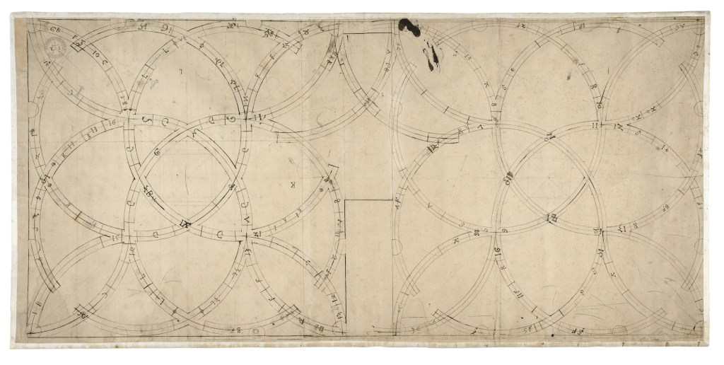
A drawing of a vaulting plan for the Chapel of Saint Catherine in Vienna. Photo Metropolitan Museum Of Art

If you are interested in learning more about set drawings and construction, this class on Set Construction offers detailed information about set construction, videos of basic flat and scenery construction, and 3D models of standard scenery pieces that will work in most 3D modeling programs.

The class includes a full set of drawings for a typical set, including 3/4″ details and FSDs.

A full set of seven sheets of drawings is part of the course.

Traditional Mexican Architecture Style Books

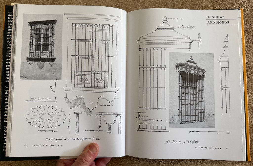
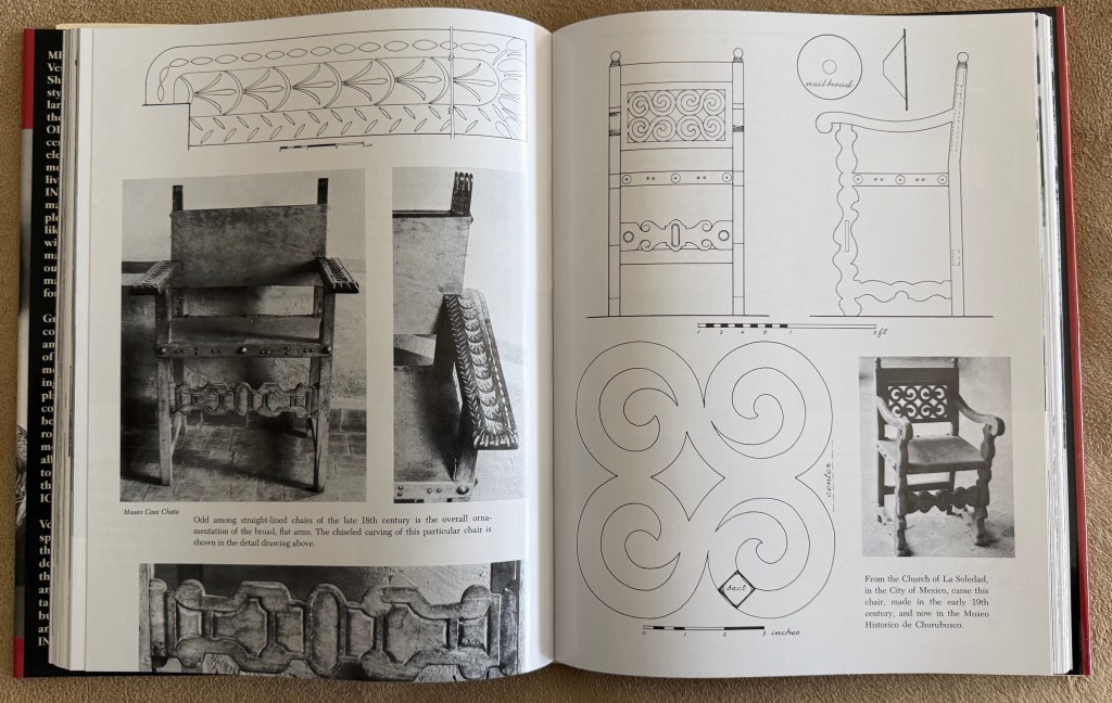
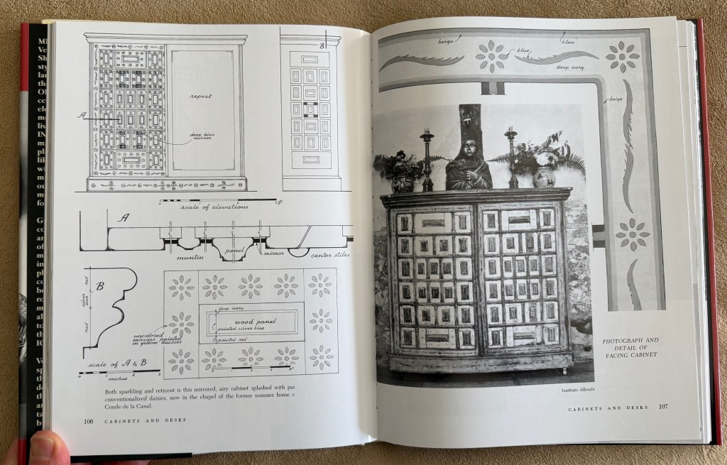
There are several books on domestic Mexican architecture that are well worth having but it is usually hard to find good copies of them because they were published over 60 years ago.

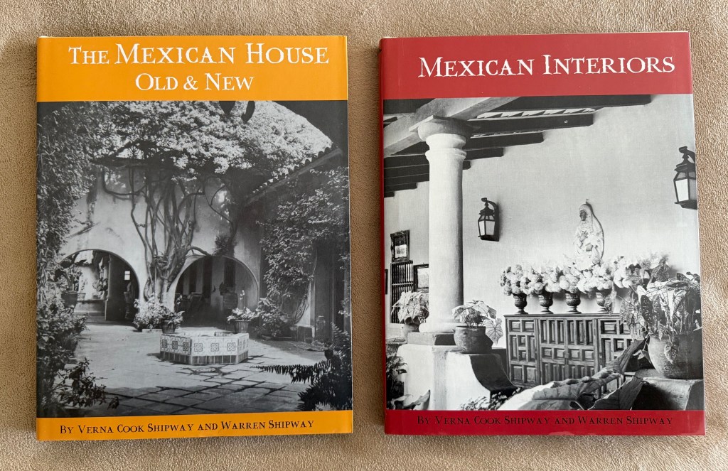
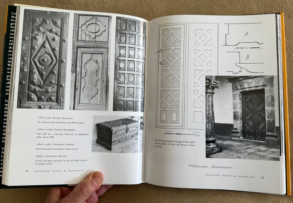
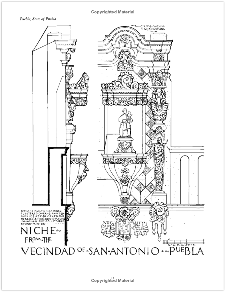
In the early 1960s, Verna and Warren Shipway wrote two books on traditional Mexican domestic architecture which were a series of black & white photographs accompanied by measured drawings of various details of the houses that they documented. The Mexican House – Old and New, was the result of years investigating the various influences on the typical Mexican house.

The follow-up book, Mexican Interiors, dealt more with furniture and other furnishings but includes architectural elements as well and follows the same layout of photos layered with measured drawings.
Both books have been republished by Hennesey & Ingalls, the architectural bookstore in downotown Los Angeles, California, in the same format as the 1960s editions. These are signature bound hardcover books and won’t fall apart like soft cover books do.
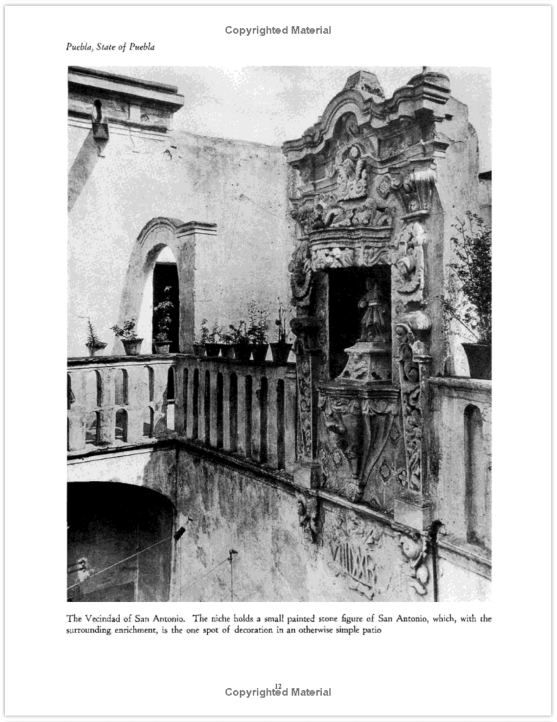
Another book done in the same style from 1930 is Early Mexican Houses: A Book Of Photographs And Measured Drawings. This book was created by G. Richard Garrison and George Rusty, two young architects in the late 1920s who spent five years documenting domestic Mexican homes when they found that there was very little available literature on the subject.

This book has also been reprinted, although as far as I know, new copies are only available in a sofcover version.

The Full Story – The Blade Runner Vid Phōn

Sometimes what you hear about a famous movie prop doesn’t give you the full story.

This is the real story behind the design of the Vid Phōn, the video phone booth in Ridley Scott’s film Blade Runner, that Harrison Ford’s character Decker, uses to call Rachael (Sean Young).

The Vid Phōn Hero prop. Now in the collection of the Academy Museum of Motion Pictures in Los Angeles. Syd Mead is given sole credit for the design on the signage at the Academy display but the prop was completely redesigned by Tom Southwell during pre-production.

Syd Mead did a lot of concept illustration work for the film that contributed to the futuristic look. But as is true for a lot of concept artwork, the execution of it can become problematic when it comes to translating it into a 3D ‘shootable’ reality.

Tom Southwell, who is a Production Designer in his own right, (Disturbia, The Salton Sea) was the production illustrator on Blade Runner, as well as many other films, and designed all of the graphics for the movie. He was also called upon to design hero props for the film that not only had to work but be ‘shootable’ as well.

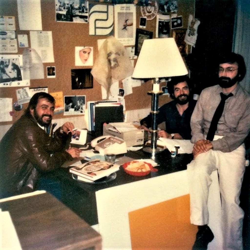
In the Art Department on Blade Runner. L to R – Production designer Larry Paull, Production Illusrator Tom Southwell, Art Director David Snyder.

This weekend, on February 28, Tom will be awarded a Lifetime Achievement Award for his work as an Illustrator and Production Designer at the Art Directors Guild Awards Banquet in Los Angeles.

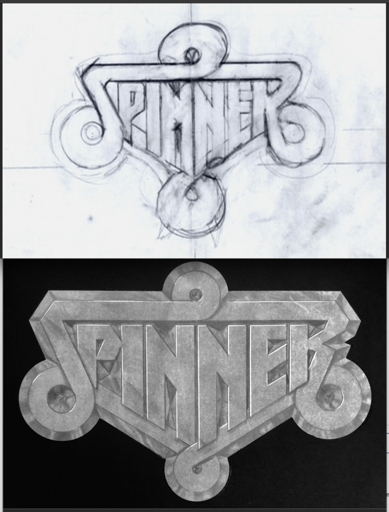
Tom’s original sketch and final logo for the Spinner Car
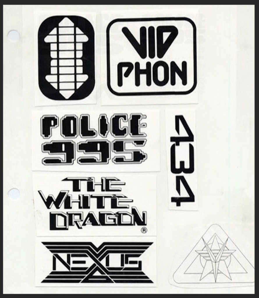
Some of Tom’s other graphics for the film.

Sometimes Unwanted Holes Aren’t So Bad

You’ve probably never thought about how sound can affect your stage set. Beyond trying to not create an environment that would drive the sound recordist mad, you usually don’t think about odd acoustic anomalies that might pop up that you never intended to happen. Like echoes.

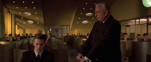
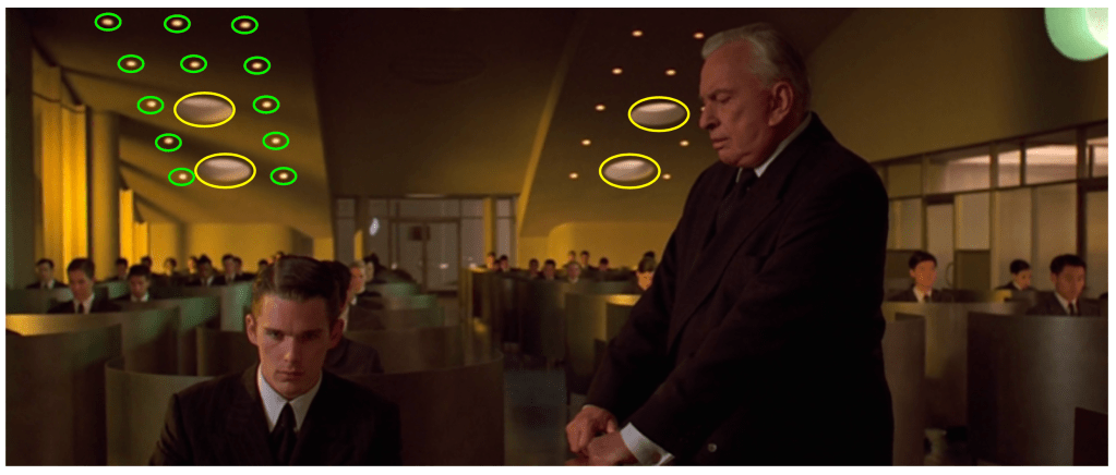
Computer Hall set – Gattaca – Columbia Pictures 1997

Yeah, echoes will bite you in the ass if you’re not careful.

On the main set for the 1997 film Gattaca, just such an anomaly occurred, and it was the cinematographer who ended up saving the day.

And what does the cinematographer have to do with sound problems? Keep reading.

The Computer Hall set was designed by Production Designer Jan Roelfs and was inspired by the real-life location that he and Director Andrew Niccol chose for the film. The actual building chosen for the exterior of the Gattaca Aerospace Corporation was the Marin County Civic Center in California, designed by Frank Lloyd Wright. The art department flew to Marin and surveyed the interior details so that they could be matched for the set on stage, which was in a warehouse in Playa Vista.

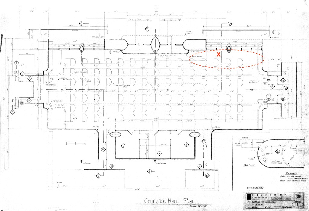
The building they had leased made for an odd sound stage, but its size made it large enough to build the sets for the film in. There were the normal problems you deal with in a structure that was never designed to be a sound stage: support posts at regular intervals, a ceiling that is not nearly as high as those in an actual sound stage. On the plan below, you can see where the oval columns were designed to hide two of the building’s I-beam columns.

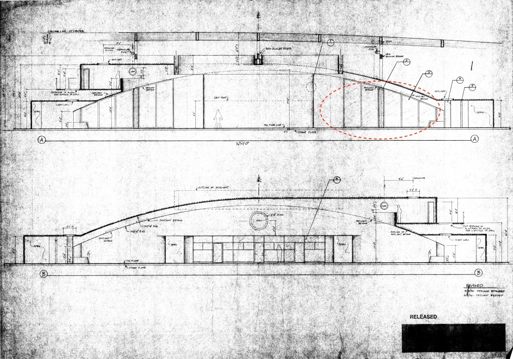
These are my drawings of the plan and elevations of the set with the areas of the sound problems circled.

(One note: on the title block, you’ll notice it reads “Eighth Day”. This was the original title of the film. In pre-production, the producers learned that there was a French movie of the same name that was going to be released, and a name change was required. The writer and director Andrew Niccol decided that he would create a new title using the four letters used to identify the nucleobases of DNA: GATC.)

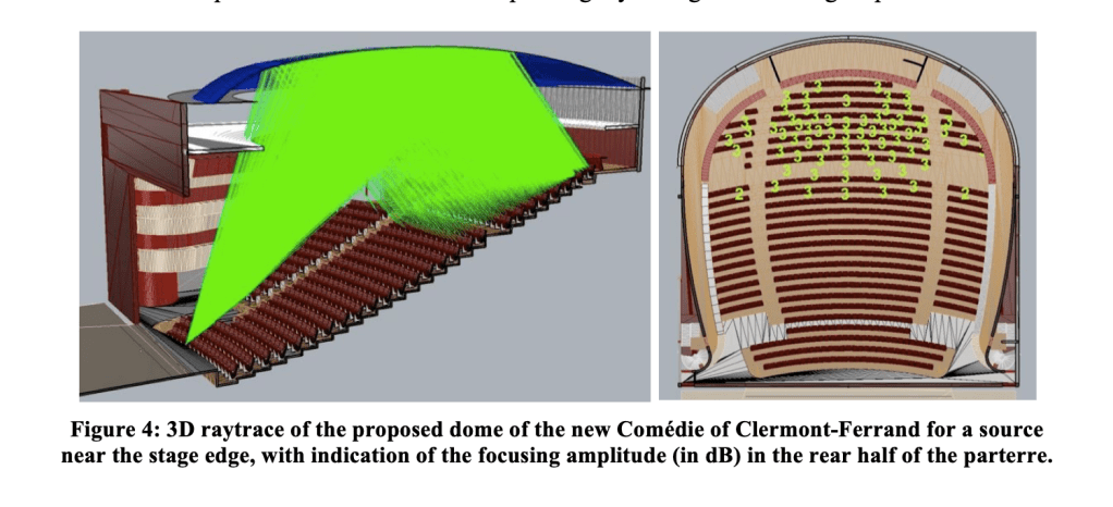
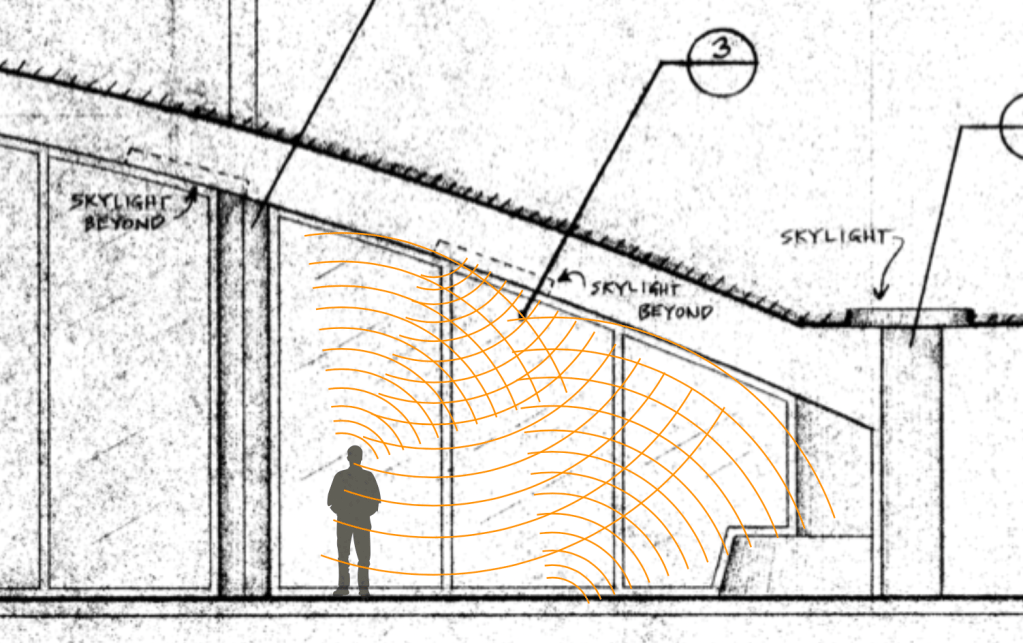
Turns out, theater designers had known about the sound reflective effects of elliptical and parabolic ceilings for years, as most of the western world designed theaters in the mode of the typical Italian horseshoe layout plan.

A presentation at the 2017 International Congress On Sound was focused on this phenomenon.

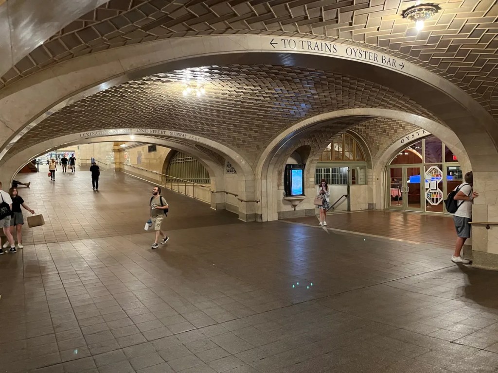
In New York City’s Grand Central Station, there is a ‘whispering gallery’ or acoustic vortex. This is an architectural phenomenon created by a number of configurations, in this case, a vaulted ceiling in the subway entrance under the terminal. A person standing in one corner of the hall intersection can whisper into the corner and the sound travels over the curved surface of the ceiling and can be heard by a person standing in the opposite corner.

New York Grand Central Station

I discovered the echo one day when I was walking the set and stopped at the point in question. I saw a gnat and clapped my hands together to kill it. That’s when I heard the strange echo. Horrified, I clapped again and there was the same echo. I clapped a third time, just as Jan was walking through the set. He stopped and frowned. “Don’t do that!’, he said.

I think what was happening was that the area beneath the lower section of the ceiling of the set created a flutter echo, which was enhanced by the smooth ceiling surface. The two large skylights didn’t seem to affect this echo.

There was no carpeting or fabric to dampen the sound which would have eliminated this effect.

The solution came for the most part when the cinematographer, Slawomir Idziak, told us that he needed more practical lights in the set. This required creating dozens of new openings in the lower sections of the ceiling. These holes interrupted the acoustic waves and the echo disappeared. With the addition of the desks and the background actors, the sound reflection was minimal.

The photo below shows the original skylights in yellow, with the new lights circled in green.

The Art Of Technical Drawings

The look of construction drawings for film and television has changed a lot over the years, particularly now that most drawings are done digitally with computers rather than by hand.

While many current drawing styles now incorporate photo-textures, shadows, and icons to add life to drawings beyond what is typical of architectural drawings, it’s hard for them to match the aesthetics of hand drawings.

CAD drawing from 3D model – photo textures applied

Having started as a pencil draftsman I guess I do have a bit of a personal bias, but the unique style of each person on a hand-drafted drawing was immediately recognizable to people who knew their work.

Before digital illustrations and renders of 3D models, hand-drafted drawings had to serve as a design sales tool as well as instructions for scenery construction.

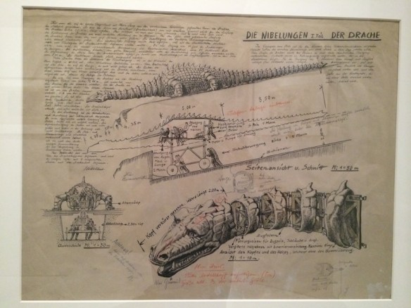
Here are some shots of a set design by Erich Kettlehut in 1923 for the UFA film, Die Nibelungen, for the scene where Siegfried kills the dragon.

The drawing was displayed as part of an exhibition of artwork from the UFA silent film period of the 1920s and 30s at the Los Angeles County Museum of Art in 2014. The drawing is from the collection of La Cinématiquè Française in Paris, France.

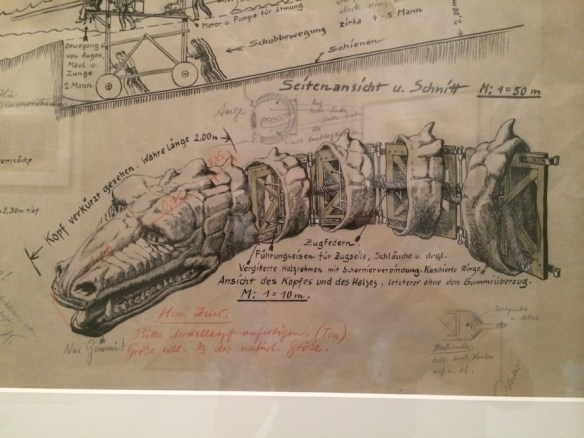
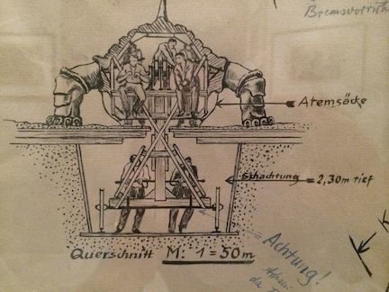
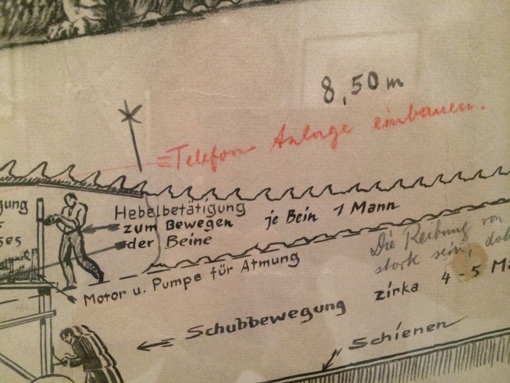
Note that the drawing not only provides a pictorial description of what the dragon should look like, but calls out dimensions, construction materials, how the action prop is to be operated, surrounding scenery requirements, and specific technical details of mechanical movements.

Technical drawing of the Dragon by Art Director Erich Kettelhut – ink and pencil on vellum
Kettelhut called out the length of the neck as well as the tension springs, framework, control cables and hoses required for the creatures fiery breath. He calls out “only rubber!” for the mouth area.
The size and depth of the recessed path required for the props operators.
drawing describing how each part of the dragon was to be operated by stagehands.
Note in red indicates that a telephone/communication system needs to be added to the prop for the crew.

The scene where Siegfried slays the dragon in Die Niebelungen from 1923

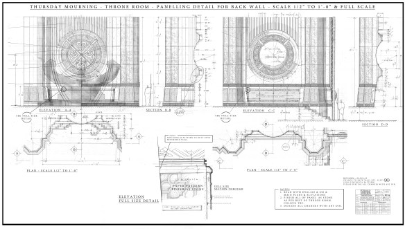
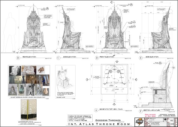
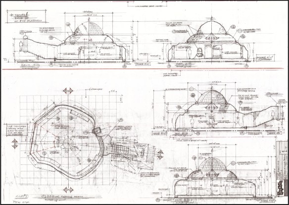
Here are a few more hand-drafted pencil drawings from more recent films:

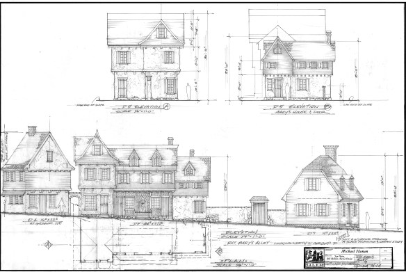
Salem – drawing by William Ladd Skinner
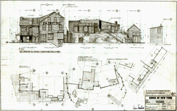
Gangs Of New York – drawing by Luca Tranchino
Shazam – drawing by Greg Papalia
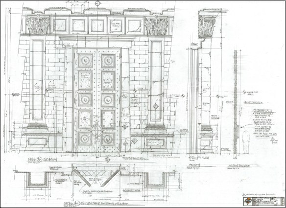
Haunted Mansion – drawing by Barbara Mesney
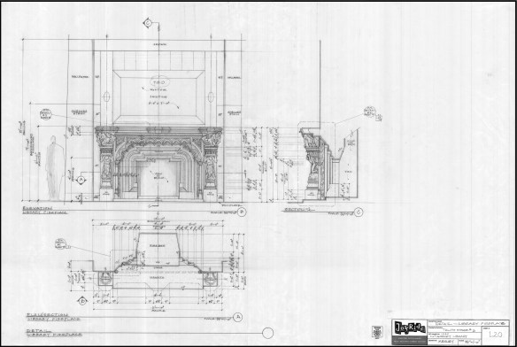
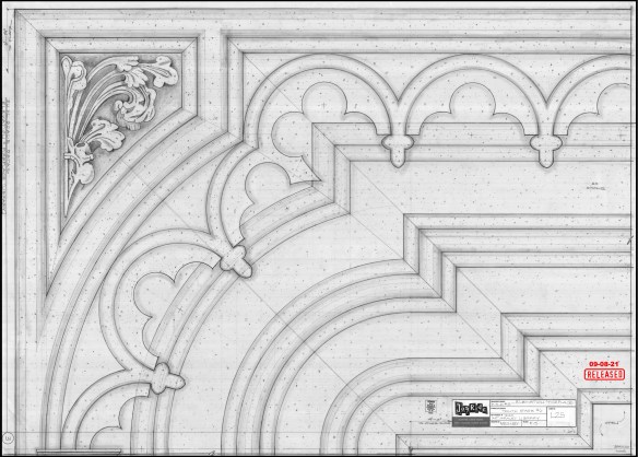
Haunted Mansion – full size detail of fireplace for the plasterers
Thor – drawing by Oli Goodier
Shazam – drawing by Stella Vaccaro
Disturbia – drawing by RD Wilkins
Haunted Mansion – drawing by Hugo Santiago
Baby’s Day Out – window detail

R.D. Wilkins