The Bounty in 2010. photo by Ebyabe
On October 29, as Hurricane Sandy bore down on the U.S. east coast, a distress call went out to the Coast Guard from the crew of the HMS Bounty. The ship was four days into a bid to avoid the ship being destroyed in harbor by the storm. The captain had decided that the best way to save the ship was to go to sea and sail around the hurricane. Now being swamped by 30 foot waves, the crew was forced to abandon ship. The captain and one of the crew were lost at sea before the remainder of the crew were rescued by Coastguard helicopters. Hours later I saw a photo of the ravaged ship as it went down, its’ mast tops shredded and its’ yards torn away.

The HMS Bounty goes down off the coast of North Carolina. Photo by Petty Officer 2nd Class Tim Kuklewski/ /U.S. Coast Guard via Getty Images
I looked at it and remembered climbing the shroud lines up to the main mast top and looking out to sea almost exactly 18 years before while surveying the ship for a film. It was to be a remake of the classic Errol Flynn pirate film, Captain Blood, and it would have been the most expensive film made to date. But the films fortunes were as bad as those of the Bounty turned out to be.
The HMS Bounty’s Rebirth
The ship was commissioned by MGM in 1960 for the 1962 film Mutiny On The Bounty starring Marlon Brando. Built in Nova Scotia, it was the first large vessel built using original ship’s plans. To make allowances for shooting and to hold a larger crew, the ship’s deck length was increased from nearly 91 feet to 120 feet with the beam, masting and rigging increased in proportion to the new hull length. Once the film was completed, the studio had planned on burning the ship but Brando protested and the Bounty ended up in Florida. It went through several owners before Ted Turner bought the ship and in 1993 donated it to an educational foundation where it was sent to a new home port in Falls River, Massachusetts.
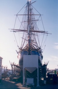
Bounty in dry dock in 1994
When we went to survey her in 1994, she was on the rails in dry dock, a number of her futtocks were in need of replacement but we were assured the work would be completed in time for filming. Three of us crawled all over the ship the entire day, taking measurements, hundreds of photographs and video to document the existing structure for as-built drawings. Since the story of Captain Blood takes place in the 1680’s, over 100 years before the original Bounty, the ship was to be converted to an earlier vessel which meant applying a different stern, rigging and bow.
The ship still had most of it’s original fittings including the brick oven and the hand grained paneling below deck. Other than the repairs on the futtocks, she seemed still intact after over 30 years of sailing.
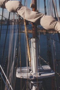
View from the main mast top. Photo- R.D. Wilkins
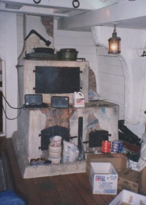
The Bounty’s brick oven. photo – R.D. Wilkins
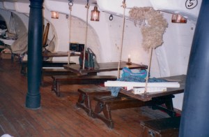
The crew mess area. photo – R.D. Wilkins
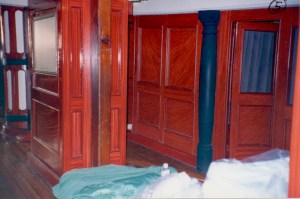
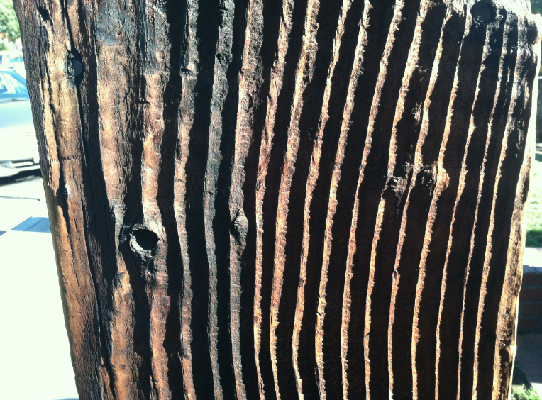
hand-grained partitions below deck. photo-R.D. Wilkins
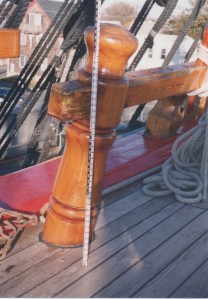
Survey photo of the fore bits. photo – R.D. Wilkins
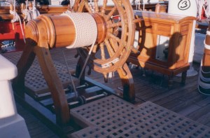
The great wheel and binnacle. photo – R.D. Wilkins
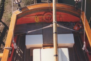
View of the stern from the mizzen top. photo – R.D. Wilkins
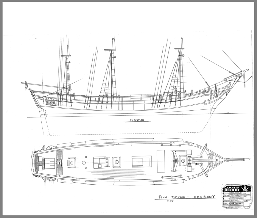
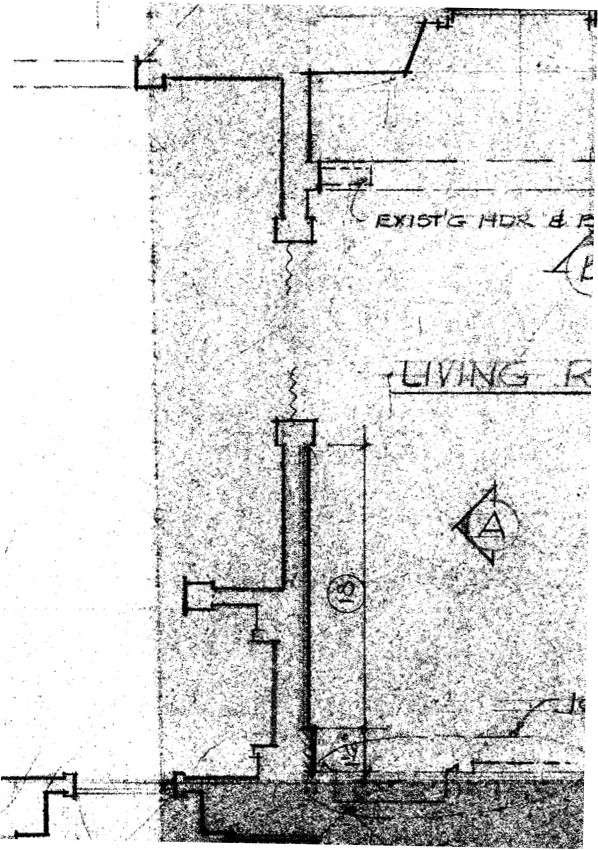
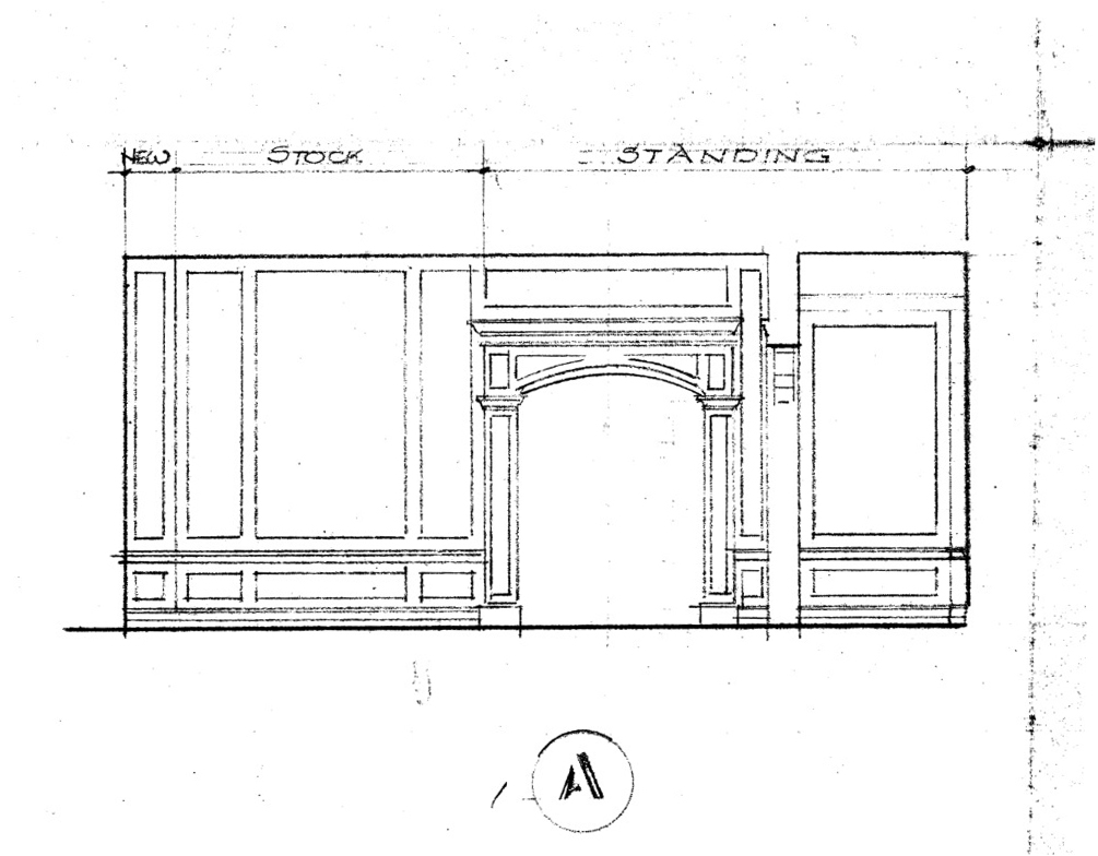
Drawing done from survey measurements in 1994. R.D. Wilkins
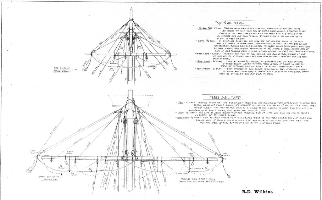
Period rigging details for Bounty conversion.
Captain Blood Sails Again
Back in Los Angeles, design work proceeded under the leadership of Production Designer William Creber, who had been nominated for Oscars three times before. The Set Decorator was Eddie Fowlie, David Lean’s right-hand man who had done props and sometimes effects as well for the classic films, Lawrence of Arabia, and fulfilled five different roles on Doctor Zhivago as well as other films. When asked by the studio which credit he wanted for Zhivago, he first replied he didn’t care but decided on a special effects credit since it had involved the most work. He later wished he had picked another title since the effects were so good they were virtually ignored. It appeared to all that the film was made in snow in winter when it was actually shot in Spain, with thousands of tons of cheap marble dust used as snow. The beautiful winter ice palace interior was actually carefully applied paraffin. He had come out of retirement to do the picture, leaving his home in Spain. We were all a bit in awe of both of them, particularly Eddie given his pedigree with Lean. The director had just had his last film explode at the box-office and was the hot ticket in town. The scripts scribes were equally hot commodities and had recent successes of their own.
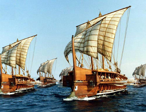
The plan was to do a remake of the popular Errol Flynn film from 1935, even though the common thought at the time was that pirate movies didn’t make money, (Jerry Bruckheimer would prove this wrong a few years later.) Popular yes, profitable no, This was mainly because of the cost involved in making them. Besides being a period film, it would involve creating a huge 17th century battle, creating at least four different period sailing ships and recreating a large section of the town of Port Royal. The initial projected budget suggested that it would be possibly the most expensive film made to date. That being the case, there were only a few stars that the studio was willing to gamble their money on, and the first choice was Arnold Schwarzenegger.
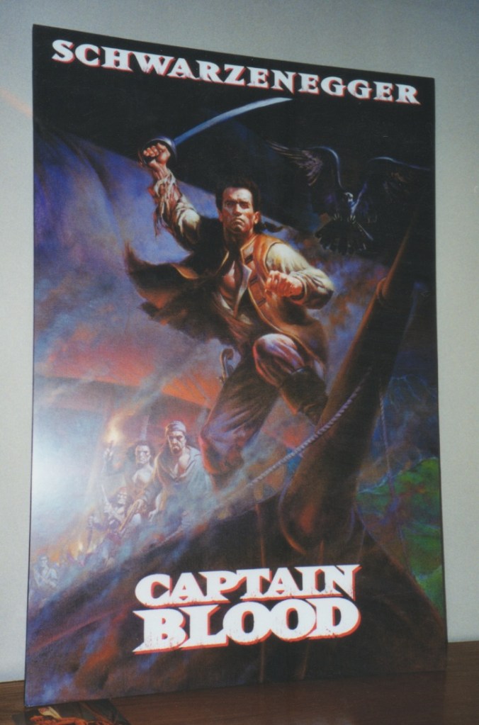
Proposed artwork for a promotional poster for the film.
I was eager to quiz Eddie about his time with David Lean but he seemed a bit aloof and obviously did not suffer fools gladly. So, I thought I would offer something he would find useful. I brought in a rare out-of-print set of books from my library of which part was an inventory of ships of the period. One section listed every piece of equipment you could find aboard with illustrations and measured drawings, a Set Decorators dream. He looked up at me over the top of his glasses when I entered his office. “Eddie, I thought these might be a good reference for you”, I said as I laid the books open in front of him.
His jaw dropped slightly as he silently thumbed through them for several minutes. Without looking up he said, “Where did you get these wonderful books?” Then he said it reminded him of how he had done the props for Lawrence Of Arabia. He had an illustrator do a drawing of each piece he needed. The he posted them on his wall and would bring the various local artisans to his office, point to the drawings and indicate how many he needed.
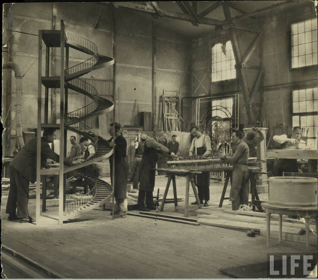
I realized why you could never make a film like Lawrence today the same way and why the Art Departments of the period were so small. Today something like a camel’s saddle would be drawn in multiple versions by several illustrators, modeled in Rhino or Modo by as many as three different set designers, rendered, redesigned, remodeled, re-rendered, finally approved by the director, and only then would a set of working drawings be made. Eddie just found a person who understood what it was he wanted, gave him a sketch and told him how many he needed. But this was a time when directors hired people they trusted and let them do their job. They understood that THEIR job was defining the story and script and concentrated on camera placement and performance and didn’t involve selecting drawer hardware.
After that Eddie would chat about he times with Lean in the afternoons at tea time, which didn’t involve tea for Eddie, who preferred beer. He’d found a local shop in Santa Monica that carried imported beer, so each day when we’d walk to lunch, ( those were the days when we actually stopped for a proper lunch and didn’t eat hunched over our desks ) we would buy him two cans of his favorite beer.
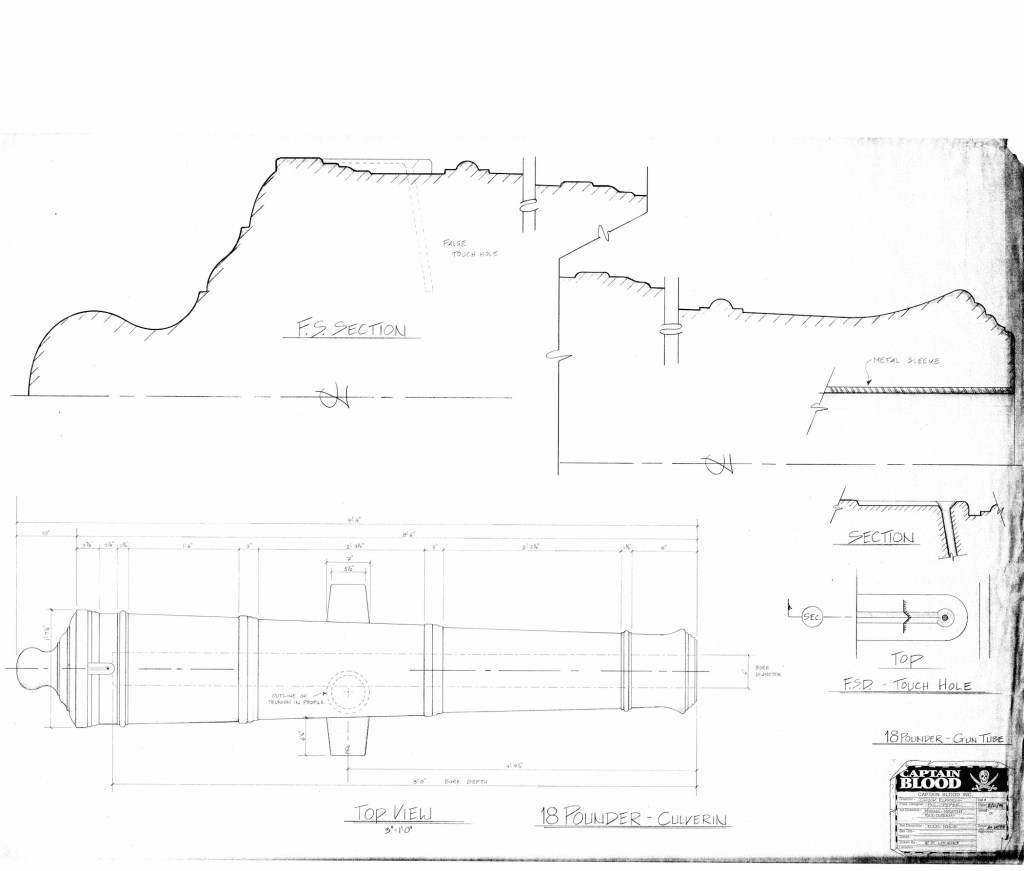
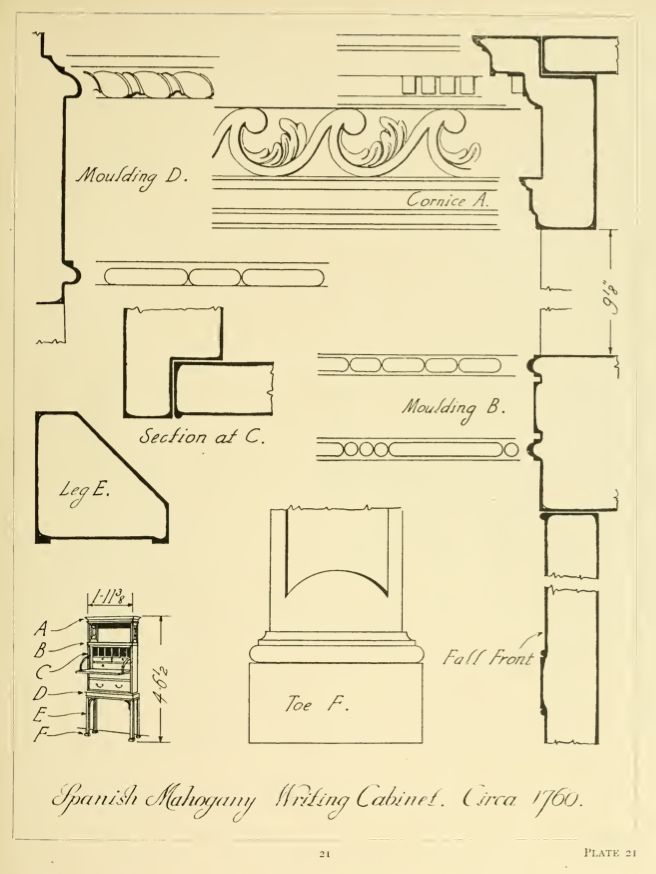
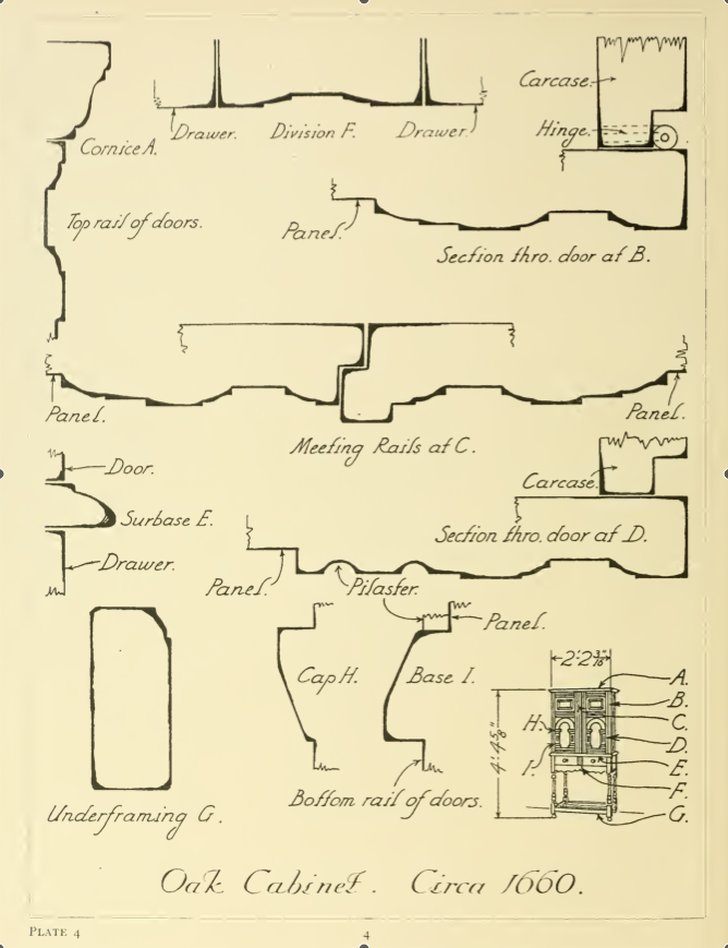
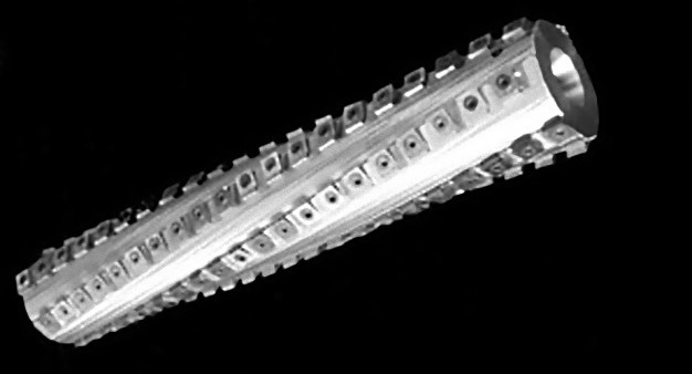
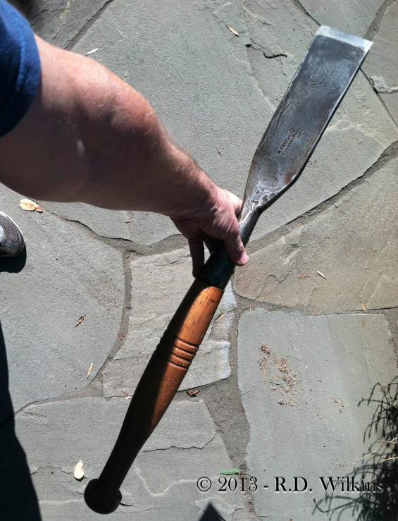
Drawing for 18 pounder cannon tubes. At over 9 feet long, these were even shorter than the largest guns to be made.
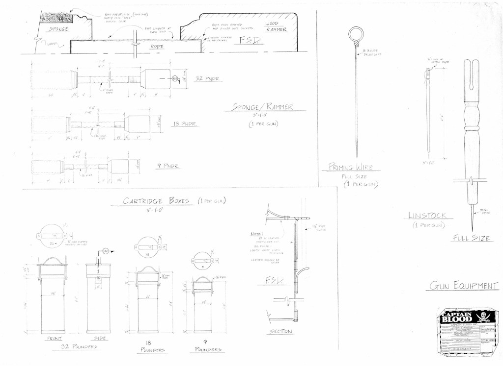
drawing of gun equipment
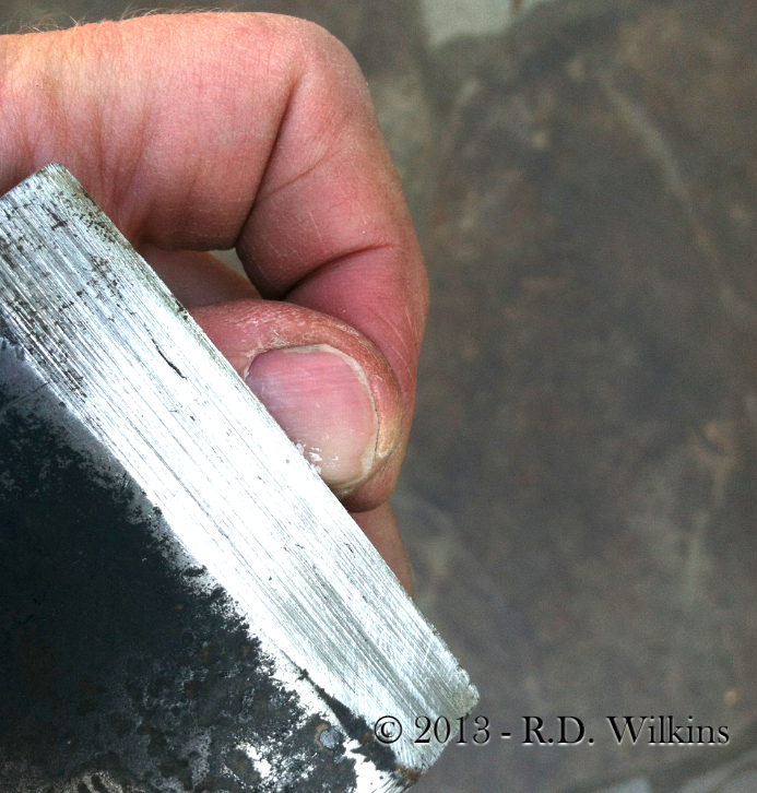
One day one of the producers was talking about the ship cannons and I showed him a mock-up of the cannon shot for the large 32 pounder cannon. He frowned as he took the 6 1/2 inch diameter ball and said it seemed puny. I walked him around the corner to where I had taped a full size silhouette of the gun that fired it, which was over 10 feet long and more than 4 feet high. He was shocked. It was then that I made the mistake of mentioning that the opening battle scene was based on a real battle, the Battle of Sedgemore in 1685. He looked surprised and said, “you’re kidding?” I said that not only was that based on history but the main character was also based on a real man named Henry Pitman. “That’s fantastic!” he said. I’m sure in his head he could see that sought-after card ‘based on a true story’ in the title sequence at the front of the film.
This revelation caused a lot of excitement and they asked me to do a little presentation for the director and producers about the real events behind the film. A few days later when I began the presentation, the enthusiasm quickly died. As I told them the real story it became readily apparent that serious liberties had been taken in Sabatini’s original book and worse, the events portrayed in the script didn’t match the real story either. The carefully crafted battle scene that took place at night in the swirling snow had actually happened in the middle of July where heatstroke would have been more a likelihood than frostbite.
It was then that I realized two important truths about the film industry;
1. – Working on a film about a subject you know a lot about is usually a very frustrating and ultimately disappointing experience.
2. – If someone, other than the Production Designer, says they want to know what it really was or looked like, it doesn’t necessarily mean they’ll change what they already have in their mind.
Most people just want research that is going to confirm or validate what they already have in the script or the image they have in their head. Maybe that’s human nature but it’s the same reason composers hate the temp music used during editing. After months of hearing a tune connected to a picture the director will end up wanting something “just like that tune”. It’s almost routine for a director to question a designer’s design choice by demanding to see research. And then when the image which validates the design is produced, the director will insist, “well, I still want my version instead.” Research that doesn’t validate their own ideas is worse than useless to them because it just points out their own ideas are many times based more on Hollywood clichés than reality.
Everything was proceeding nicely when we be can to hear rumblings that Schwarzenegger was thinking about pulling out of the movie. It was rumored that he had an extended ski trip planned that conflicted with the schedule. Someone else suggested that he was worried he would look ridiculous in 17th century knee breeches. For whatever the reason, a week later it was confirmed that he had pulled out of the picture. The momentum slowed to a crawl. With a picture this large, particularly a picture partly shot at sea, the weather plays a large role. If the schedule was pushed we would be into hurricane season in the tropics and that was something the studio didn’t want to contemplate. Another actor would have to be found and fast.
Because of the estimated budget, the studio sent a list of just five other actors that they considered to be enough of a box office draw to make the film feasible. I leave it to you to guess who those five were. As the week went by, each actor on the list passed until there was just one who had yet to decide.
In my naiveté, I had regularly been collating and forwarding research from my library that I though would be useful but never got a response about it. As each script revision happened it became apparent that it was being tailored to Arnold’s action hero persona with ever greater feats of daring and super-human agility. That last Friday, I got a call from the director’s assistant. She asked if I could send her additional copies of the all the research I’d been sending over to the director saying that the originals had been ‘lost’. The director was scheduled to leave on a plane for Paris that evening and wanted to take the research with him. It turns out the actor who was the film’s last hope was interested, but only if it was going to be a historically motivated picture. I wasn’t sure how they were going to explain why the script was so different from the research.
I don’t think I need to tell you what the actor’s decision was.