Why You Need Full Size Details

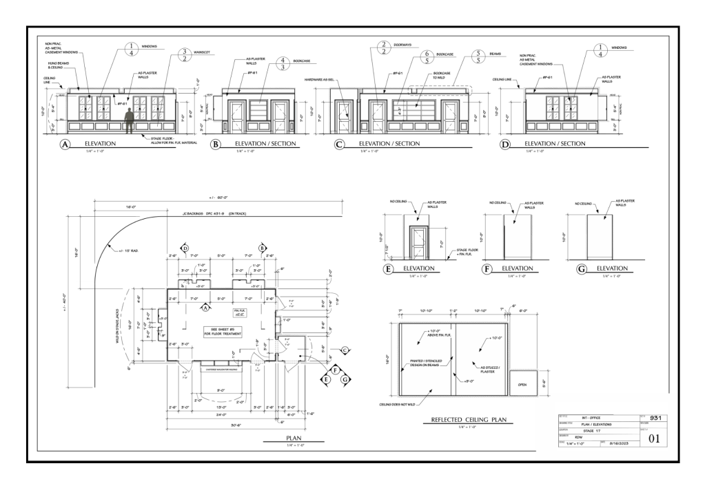
On construction drawings they are noted as an FSD, an abbreviation for Full Size Detail. You need them to visually describe exactly how something is to be built, whether it’s a built-up moulding profile or a complicated mechanical detail.

Here is an example of a typical situation where an FSD is needed. Note the red arrow pointing to a detail bubble that reads, ” FSD – 8A”. This is noting a sub-detail of a window detail labeled as #8.
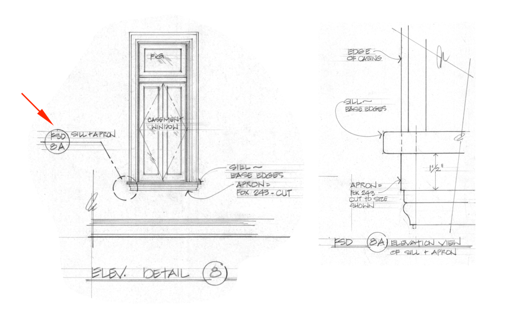
Detail drawing by Dawn Snyder

The detail calls out a window sill apron mould with the moulding profile number and a note that the moulding is “cut”. This means that rather than being used as-is, the moulding needs to be altered in some way. This level of detail is impossible to read on the elevation which is drawn at 3/4″= 1′-0″.

The FSD beside it shows how the moulding is to be placed in relation to the other window parts as well as shows that the plinth of the moulding profile is to be cut down to 1 1/2″. Unless you don’t care how the window ends up looking, you need to include FSD drawings if you have specific details in mind.

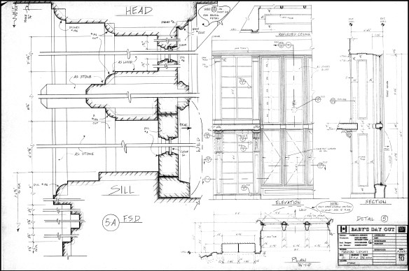
Here is another FSD through a window jamb. This drawing shows the jamb thickness, sash thicknesses and widths, the moulding profiles, architrave, and panel moulds. An FSD is needed for this complicated level of period details.
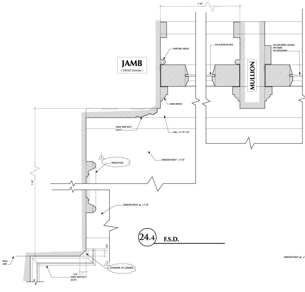
FSD Window detail – R D Wilkins

Below is an FSD of a vertical section through a platform riser. Here you can see notes as to materials, fasteners, and electrical lighting effects. Again, it’s impossible to communicate this level of detail in a smaller scale of drawing. You may encounter some situations where you can get by with a half-scale or half full-size drawings, but these aren’t recommended if a full size detail is possible.
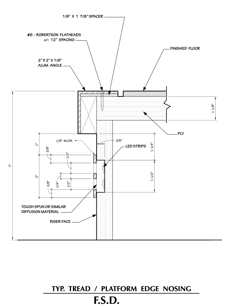
FSD platforn detail – R D Wilkins

A note on dimensioning: You’ll notice that in the section through the window jamb that there are few dimensions. Only the distances where the drawing contains a ‘broken’ wall line are dimensioned. This is traditional, as the prints were originally made as a direct contact print and the set designer was sure that the prop makers could scale from the drawing and get correct measurements. This was the point of a full-size, as you’ll see below.

Once CAD became the standard, and you couldn’t be sure that the print was made at 100%, and people began to work from prints that were smaller than intended, there was more assurance in completely dimensioning even an FSD. This is for the Art Director on a show to make a call on.

Shop Drawings & Story Sticks

There’s nothing new about the concept of full size drawings. It’s a technique that’s thousands of years old.
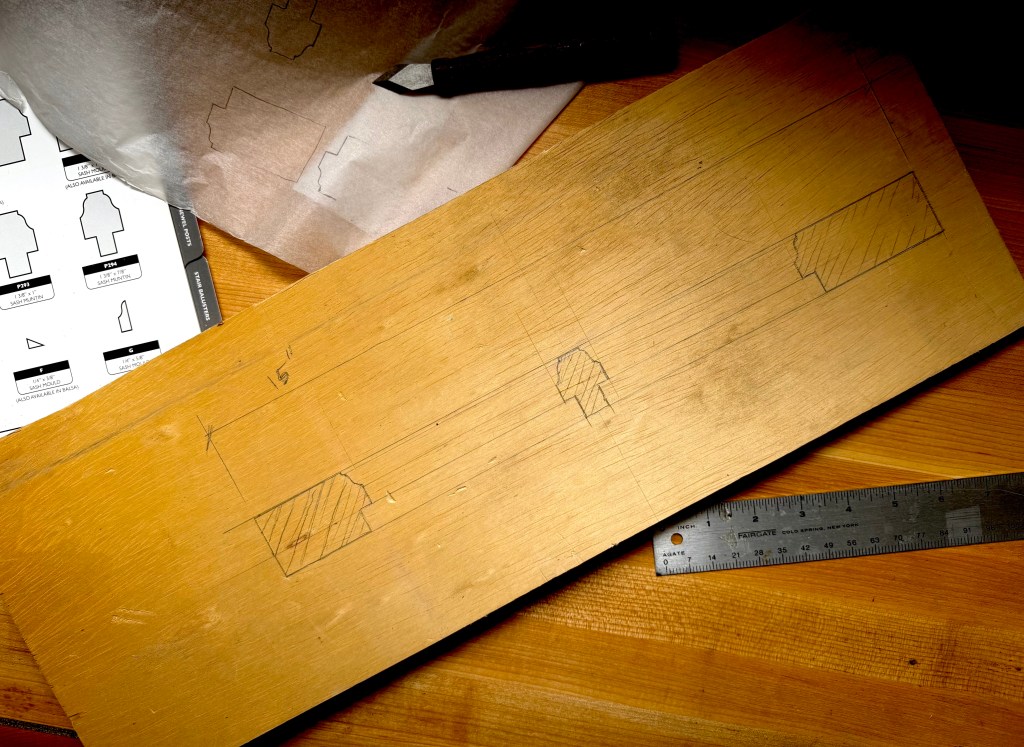
A shop drawing for a small window sash, drawn in pencil on a scrap board.

When I was a prop maker, we were trained to create shop drawings for things like mouldings, windows, and doors. On television shows there is not often time to do full size details of every set element and it often fell to us to create a shop drawing to ensure accuracy when laying out the pieces for a built object, especially a window. Nothing sucks as bad as inserting window sash into a frame and finding out the meeting rails are off by a quarter inch.

In the best case, a full size section has been drawn and you can either pull dimensions off the drawing or glue one to a piece of door skin to cut a template out on a bandsaw.

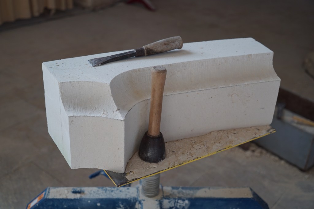
Traditionally jointers, carpenters, and stone carvers created their own story sticks or setting-out rods to be sure that their cuts were accurate, or full size patterns to check the true size of their work piece.
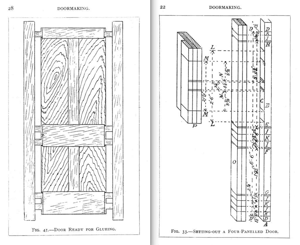
An example of a Setting-out rod for a 4-panel door. This is from a reprint of an excellent little book called Doormaking & Windowmaking from Lost Art Press.

In traditional Japanese house construction, the master carpenter would lay out all the major dimensions for a house on a master story rod called a Kensao. This was like a blueprint on a stick and would be referred to for all questions about construction measurements or additions to the structure. When the house was completed, the rod was kept in the eaves under the roof of the building.
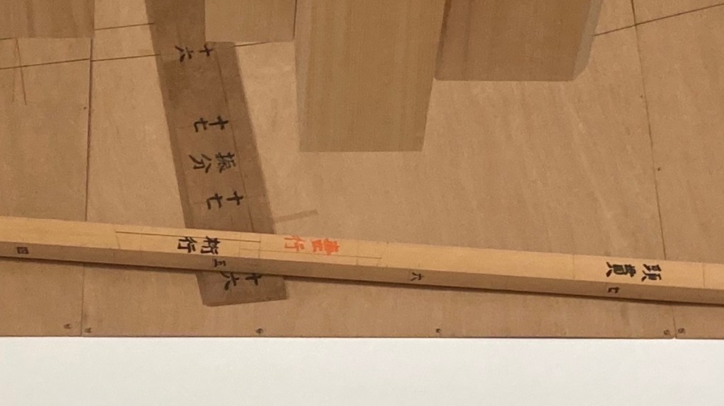
A kensao which was part of the collection of the Masters Of Carpentry exhibit at the Japanese House in Los Angeles.

In the Middle Ages and the Gothic period, stone building details were laid out in full size on a tracing floor, a floor that had a smooth layer of plaster applied to it on which the details were laid out with a large compass and straight edges that the stonemasons referred to for each separate element to make sure that they would fit together.
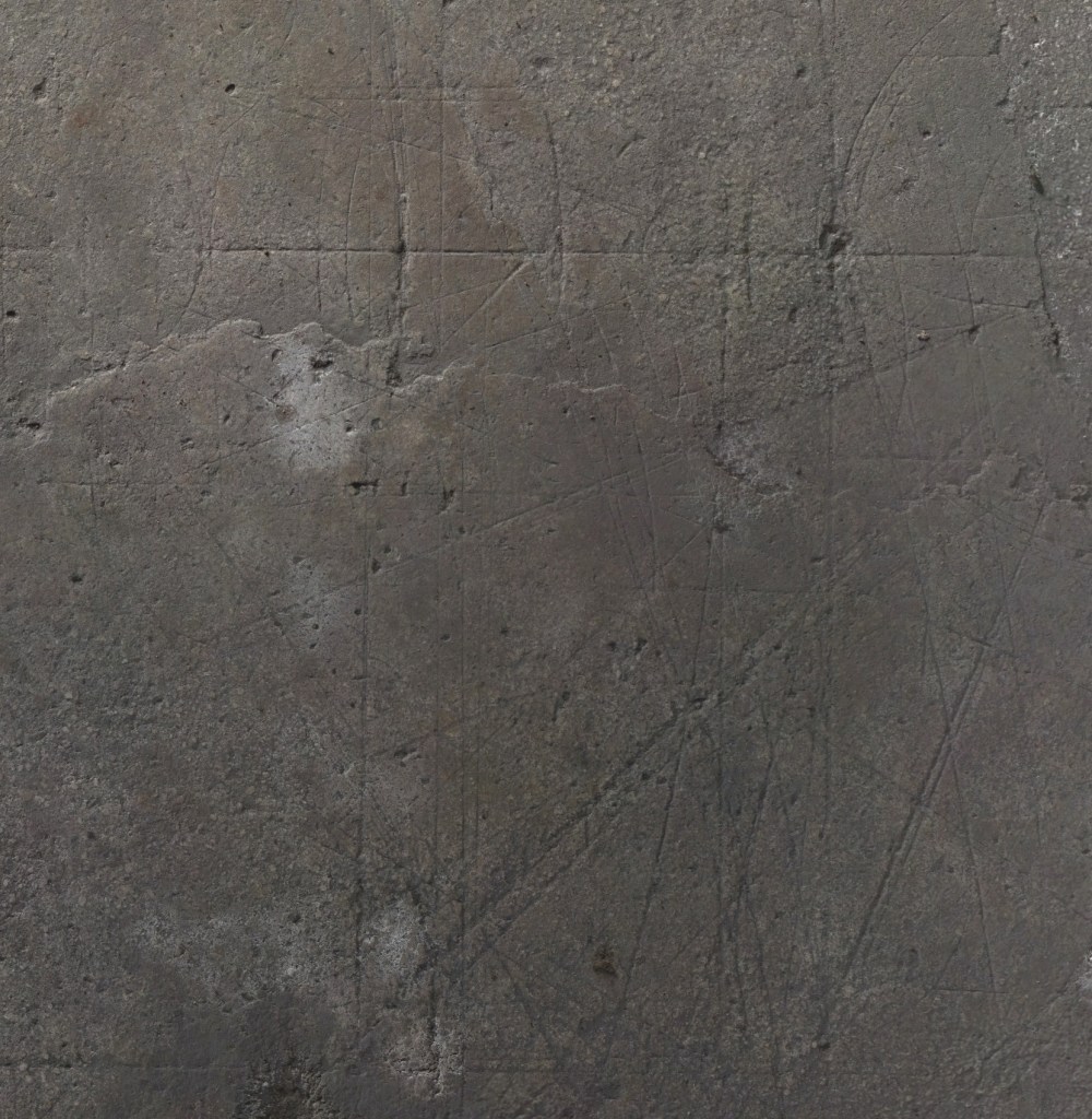
remaining images from a tracing floor

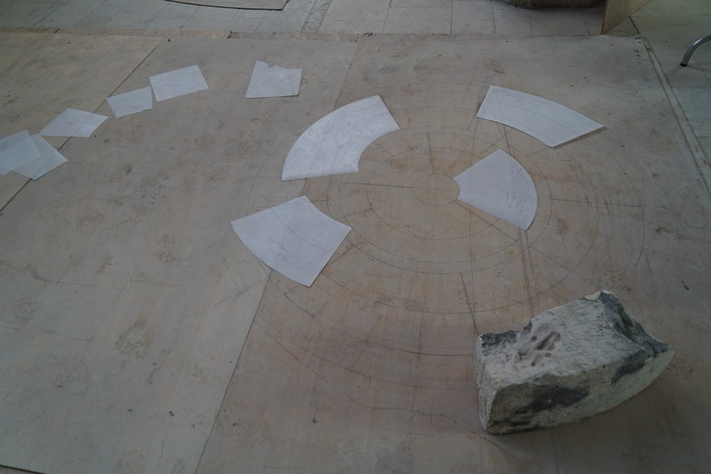
I was able to watch some stonemasons in France repair the windows of a medieval church and saw their modern day version of the original process. The design was drawn out full size on thin plywood sheets. This pattern was transferred to separate patterns on thin plastic which were then used to trace the outline onto the stone itself.
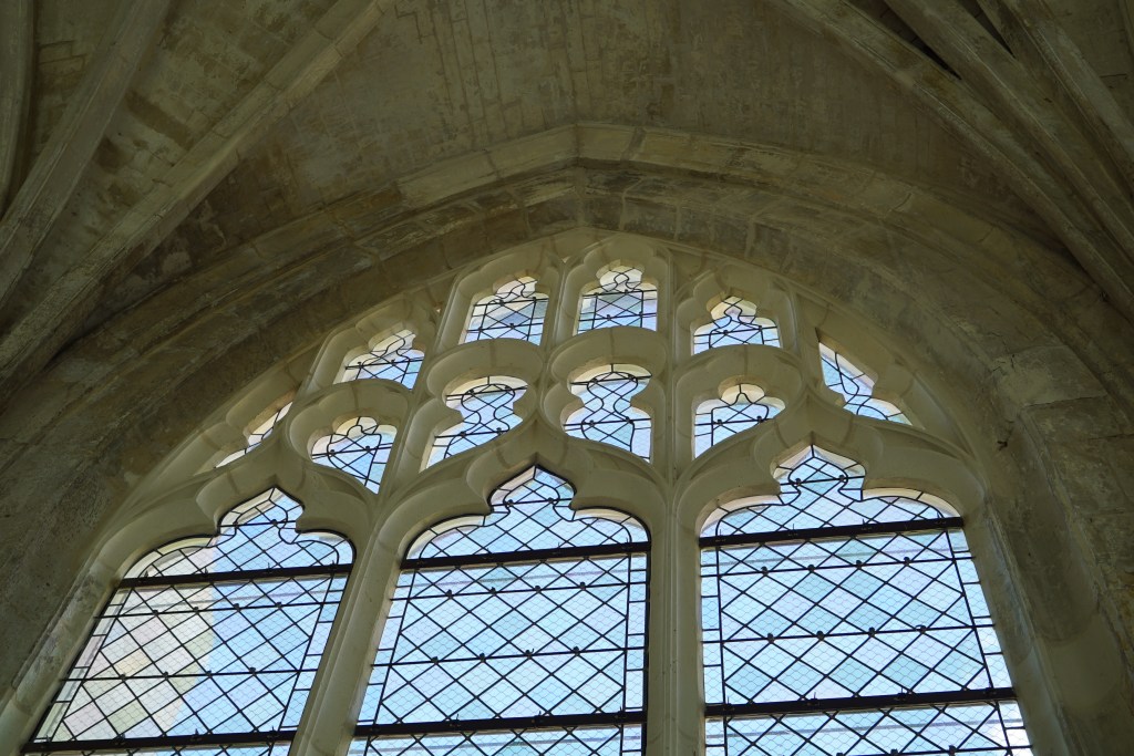
newly replaced tracery
full size detail on plywood with individual stone patterns in plastic
Individual stone tracery section in progress

Production Designer Sarah Knowles recently told me about a new exhibition at The Met in New York City. Entitled Gothic by Design: The Dawn of Architectural Draftsmanship, the show includes over 90 original pieces that span from the 13th to the 16th century. On now though July 19.

Many of these pieces were meant to be presentation artwork to show the sponsor what the final building would look like, but there are several construction drawings in the gallery show.


The Met – Gothic By Design Exhibit. Photo: Metropolitan Museum Of Art New York

One of the drawings s a plan and developed stair stringer for the Saint Stephens Cathedral in Vienna. The stairs are shown in a painting by artist Rudolf von Alt in 1841.
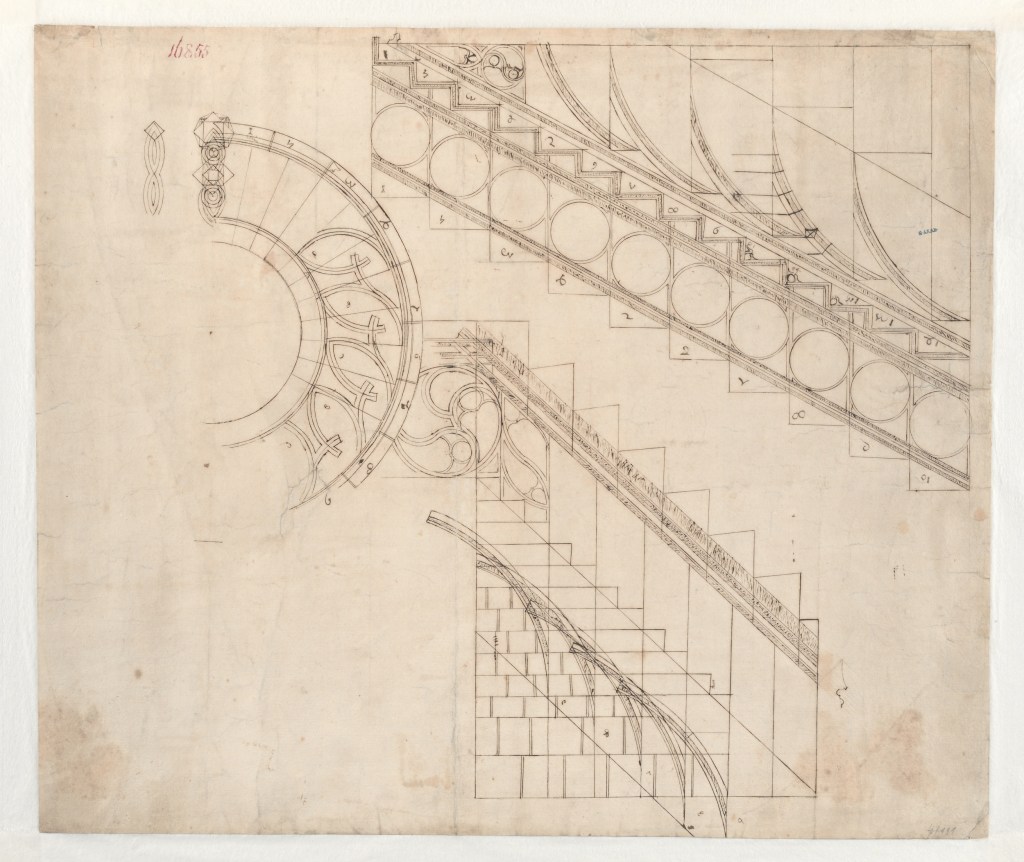
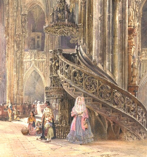
Drawing by Anton Pilgram, 1515. Photo: Metropolitan Museum Of Art, New York
The staircase is shown in a painting by Anton von Alt from 1841

The one full-size detail is of a vaulting detail from the Chapel of Saint Catherine in Vienna.

Similar to the plastic sheet patterns that the French stonemasons use today, the stonemasons of the period would make a pattern on paper for each of the stone sections.

One drawing in the collection is of the entire vault pattern with each of the pieces numbered.
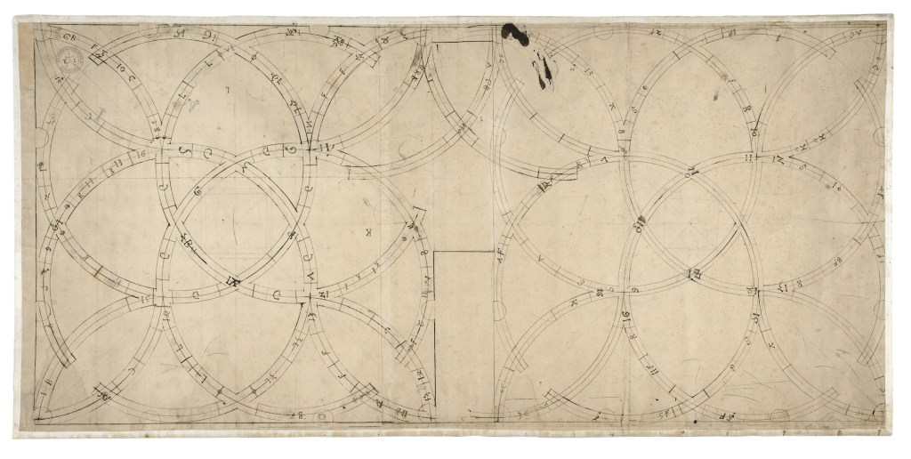
A drawing of a vaulting plan for the Chapel of Saint Catherine in Vienna. Photo Metropolitan Museum Of Art

If you are interested in learning more about set drawings and construction, this class on Set Construction offers detailed information about set construction, videos of basic flat and scenery construction, and 3D models of standard scenery pieces that will work in most 3D modeling programs.

The class includes a full set of drawings for a typical set, including 3/4″ details and FSDs.

A full set of seven sheets of drawings is part of the course.

Traditional Mexican Architecture Style Books

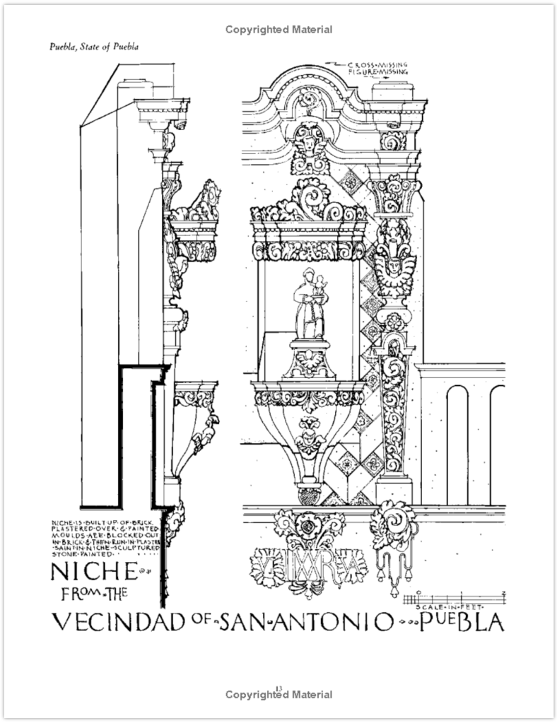
There are several books on domestic Mexican architecture that are well worth having but it is usually hard to find good copies of them because they were published over 60 years ago.

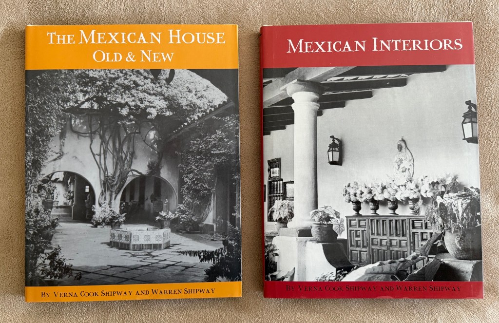
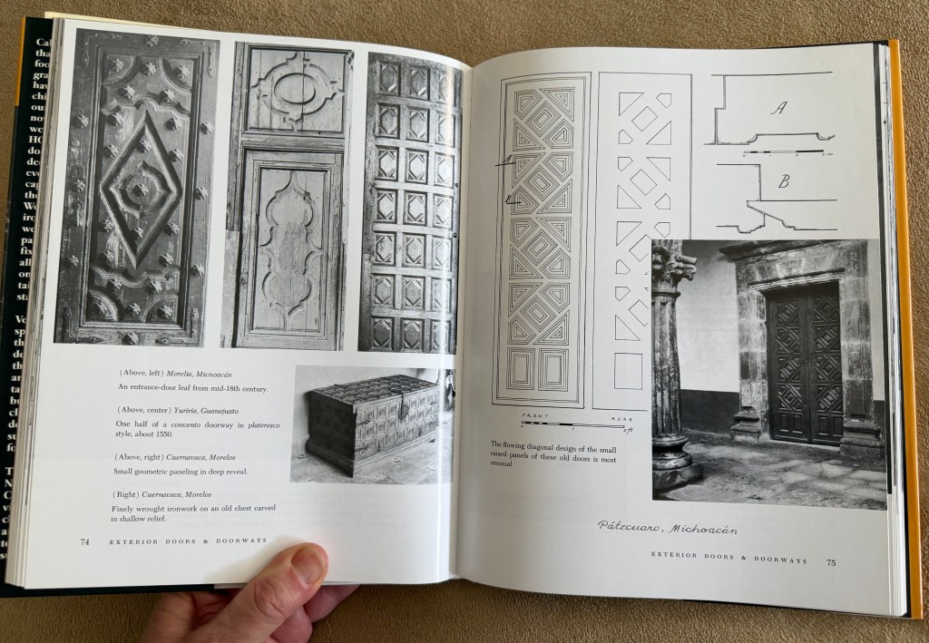
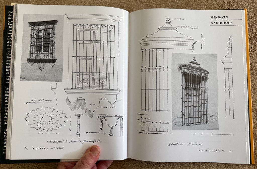
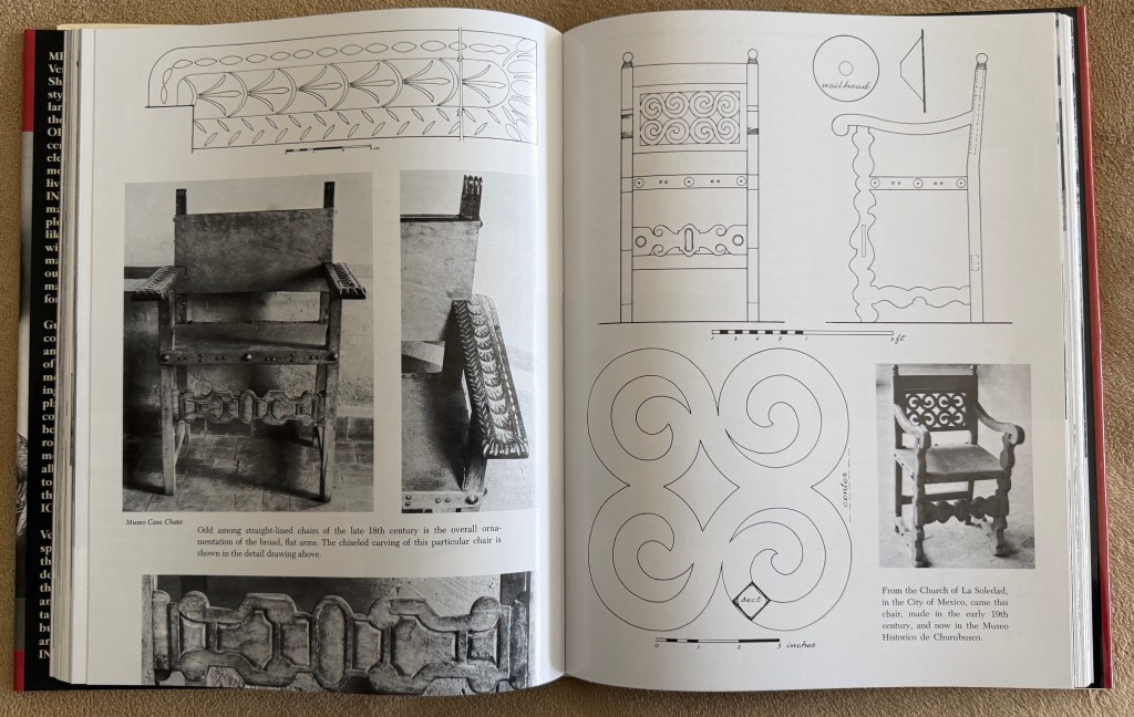
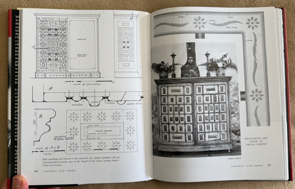
In the early 1960s, Verna and Warren Shipway wrote two books on traditional Mexican domestic architecture which were a series of black & white photographs accompanied by measured drawings of various details of the houses that they documented. The Mexican House – Old and New, was the result of years investigating the various influences on the typical Mexican house.

The follow-up book, Mexican Interiors, dealt more with furniture and other furnishings but includes architectural elements as well and follows the same layout of photos layered with measured drawings.
Both books have been republished by Hennesey & Ingalls, the architectural bookstore in downotown Los Angeles, California, in the same format as the 1960s editions. These are signature bound hardcover books and won’t fall apart like soft cover books do.
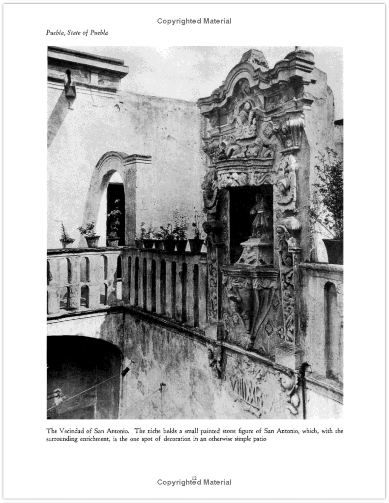
Another book done in the same style from 1930 is Early Mexican Houses: A Book Of Photographs And Measured Drawings. This book was created by G. Richard Garrison and George Rusty, two young architects in the late 1920s who spent five years documenting domestic Mexican homes when they found that there was very little available literature on the subject.

This book has also been reprinted, although as far as I know, new copies are only available in a sofcover version.

UPDATE – Graphic Standards From Across The Pond

This is an update to a post I made back in 2012 about standard European architectural manuals; Neufert’s and McKay’s Building Construction.

I’ve recently found digitized copies of both of these online and have posed them at the bottom of each of the descriptions below. Copies of McKay’s have been hard to find here in the States and I like having a digital copy to refer to when I’m on location. Less shipping!

Here in the US, the book we primarily turn to for all questions of an architectural nature is the AIA Architectural Graphic Standards. For our work, the third and fifth editions are the most informative because they were printed at a time when architects had to draw everything rather than order most elements pre-made. If you happen to be drawing up European architecture, though, it won’t do you much good.

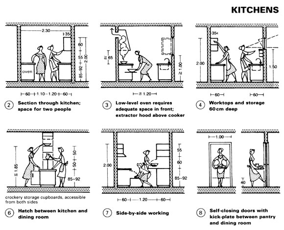
In the rest of the world, the architectural book most people turn to for similar answers is Neufert’s Architectural Data. Soon to be released in it’s 40th edition, the book is printed in 18 languages and is the architectural Bible in the metric world.

Ernst Neufert

Ernst Neufert worked at the Bauhaus as chief architect under Walter Gropius and later taught at the Bauhochschule until the Nazis closed it down in the early 1930’s. Seeing the need for a book that graphically laid out the architectural standards of the time, the book was first printed in 1936 and soon became a big success. Like Graphic Standards, the book is mainly a visual reference of architectural design and space standards for the European continent.

The book has had a number of English language editions, but the 1998 International is the most useful and easiest to use for the metrically-challenged. A large number of each edition are printed so it should be fairly easy to find used copies. You may have better luck throught British booksellers than second-hand businesses here.

A digital copy of an early edition can be found here:


kitchen standards from an earlier edition

In Britain, The book many people refer to is McKay’s Building Construction. Originally published in three volumes over an eight year period, the recent re-publication has combined them into one book. The books are so popular in England that when they briefly went out of print, students were encourage to beg, borrow or steal to get a set.

page on hand-cut stonework

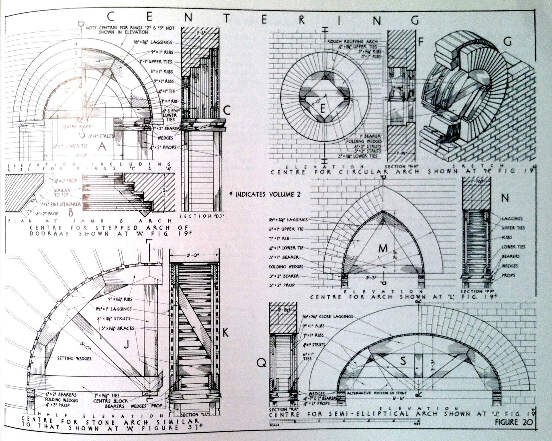
Written by W.B. McKay, who was Head of the Building Department at both Leeds and Manchester colleges, the book is particularly useful for our business as it shows and describes exactly how the various methods of construction (wood and masonry ) are carried out. Filled with hundreds of beautiful perspective drawings by McKay, the book takes up where Graphic Standards ends.

Like Neufert’s, this can be had in used editions, the most recent from 2004. I found my copy in a bookstore in New Delhi, India, so you may have to search around. This is definitely a book that is worth the search.

If you’re in a hurry, you can order it here.

Digital copies of the 1945 edition can be found here:

Volume 1

Volume 2

Volume 3

methods of forming masonry openings

Railroad & Train Car Reference

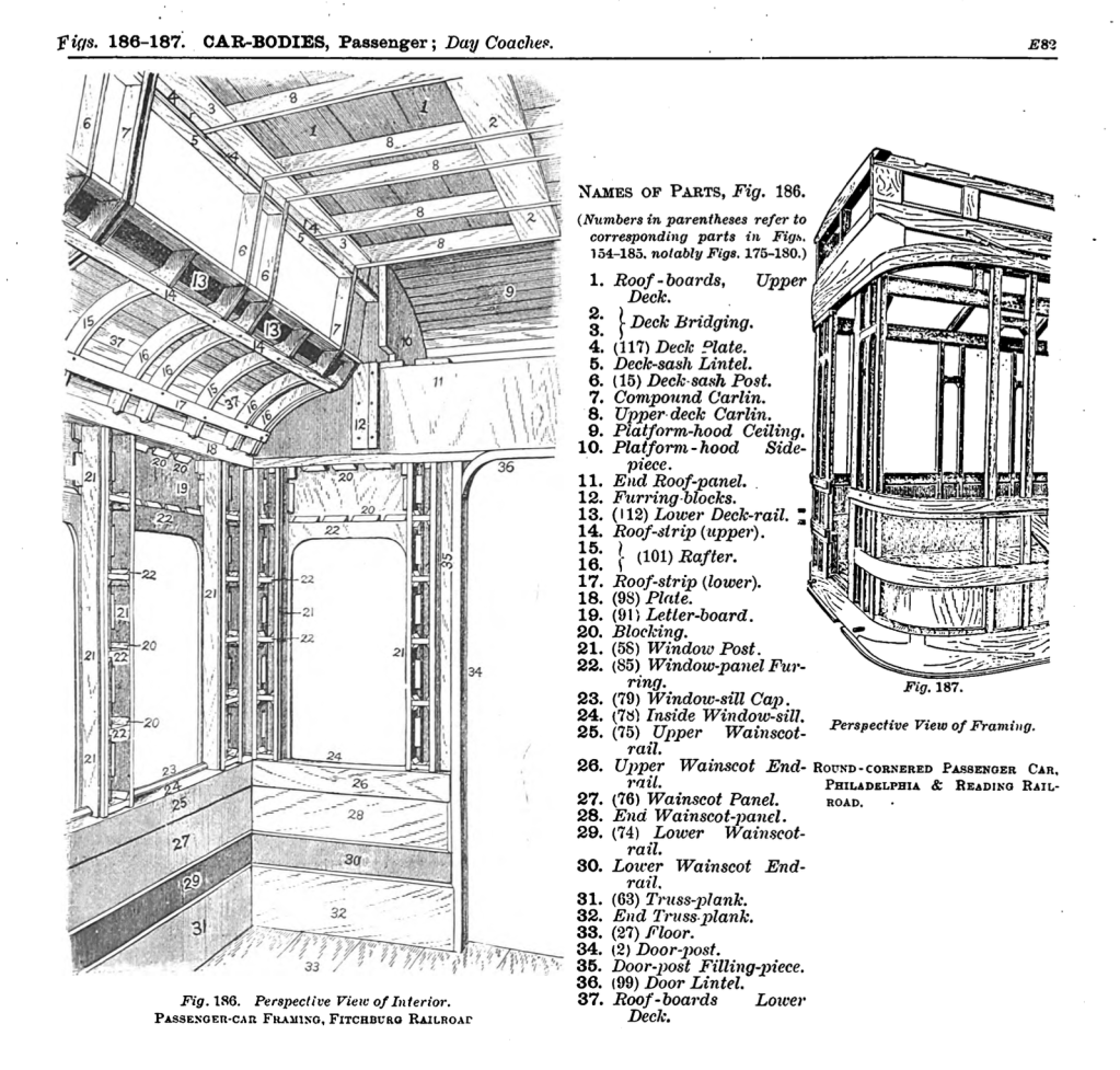
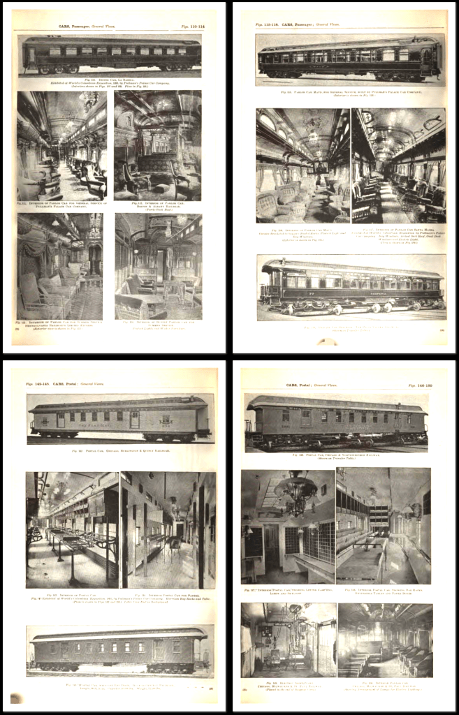
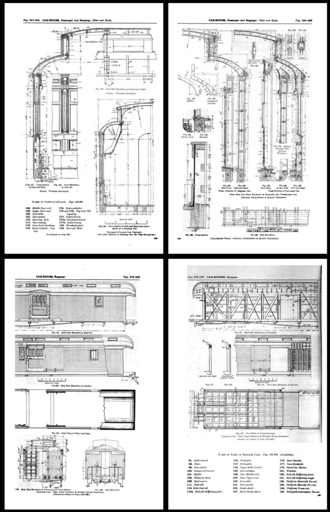
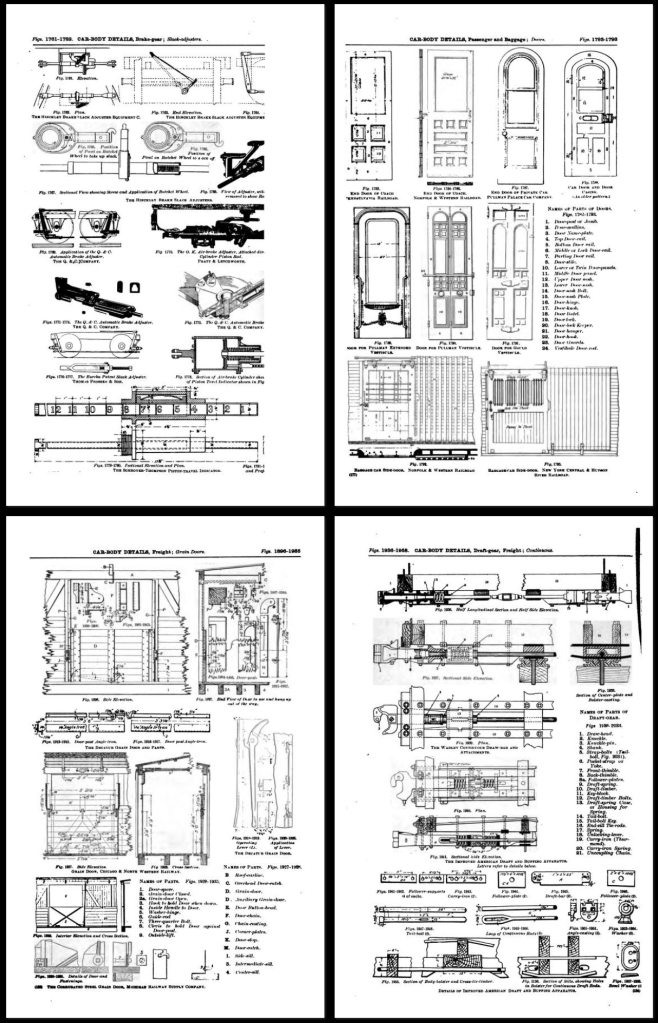
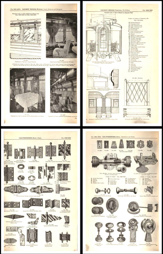
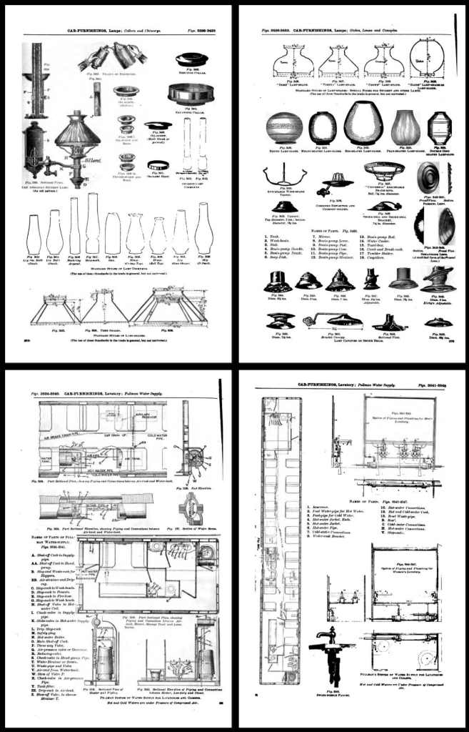
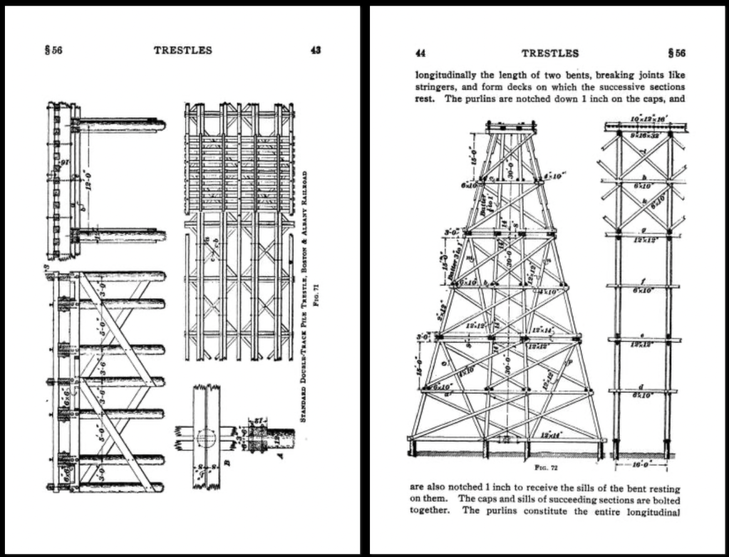
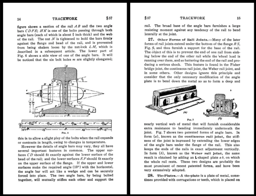
Illustrations from The Car-Builder’s Dictionary

Trains are one of those set pieces that don’t get used often anymore and reference for early period trains isn’t always easy to find. My train reference usually gets buried on a back shelf of my library and I have to unearth it when a design comes along that involves a train car or a scene that requires recreating railroad scenes.

These two books are the most complete that I’ve found when I need to create details for a train car build or most any other information on late 19th to early 20th century railroad systems.

The first is The Car-Builders Dictionary, which is now in a digital format. It’s a 680 page book that includes pretty much anything I have ever needed to know about railroad cars of that period. The book includes a 200 page glossary as well as scale drawings and perspective views of almost all passenger and freight cars, including street cars, both American and English.


A similar book which focuses more on freight cars is the 1919 Car Builder’s Dictionary and Cyclopedia.

There are scale drawings, plans, and sections of cars to show construction and layout. There are also photographs of car interiors, and detailed illustrations of every part on the cars, both functional and cosmetic: seating, hardware, brake diagrams, truck construction, lighting, etc.

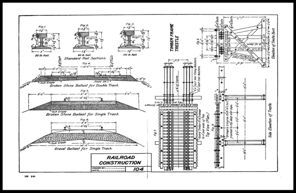
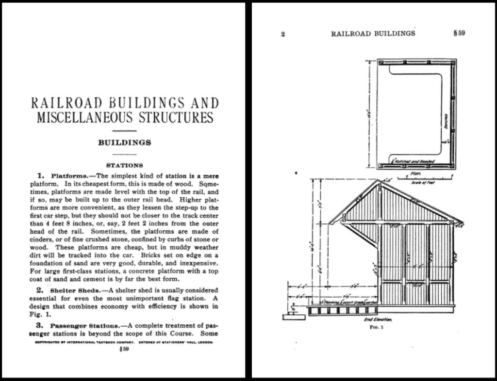
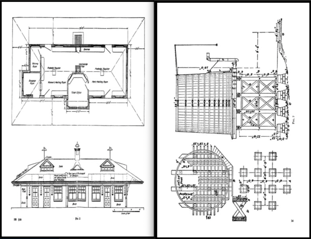
For everything else railroad related, I’d recommend the I.C.S. Reference Library, Vol. 133_Railroads, 1908. This is a 800+ page manual that covers the infrastructure of railroads, including track design and layout, covering standard track schematics, bridges, rail specs, buildings, service facilities, and sections on road and highway construction, and city surveying and survey drawings.

Wood Moulding And Proportions

When recreating a period set from the 1800’s in particular, it’s difficult to really replicate the designs of the period because current wood moulding and millwork don’t allow for what was a common practice by designers and architects; true proportional design.

A moulding catalogue of today looks very different from the original moulding catalogues of the 1800’s. Not only because they contained a larger variety of profiles, but there was a large selection of different sizes for almost every profile that they offered.

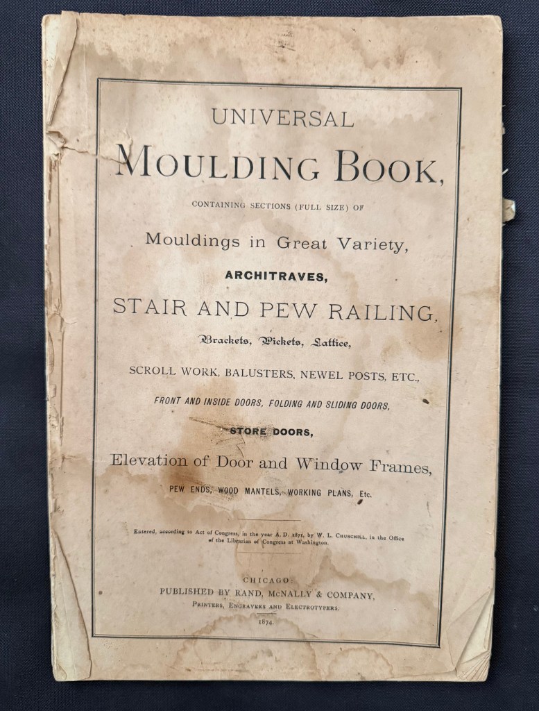
The cover of the 1874 Universal Moulding Book. One of the first millwork catalogues for wood moulding.

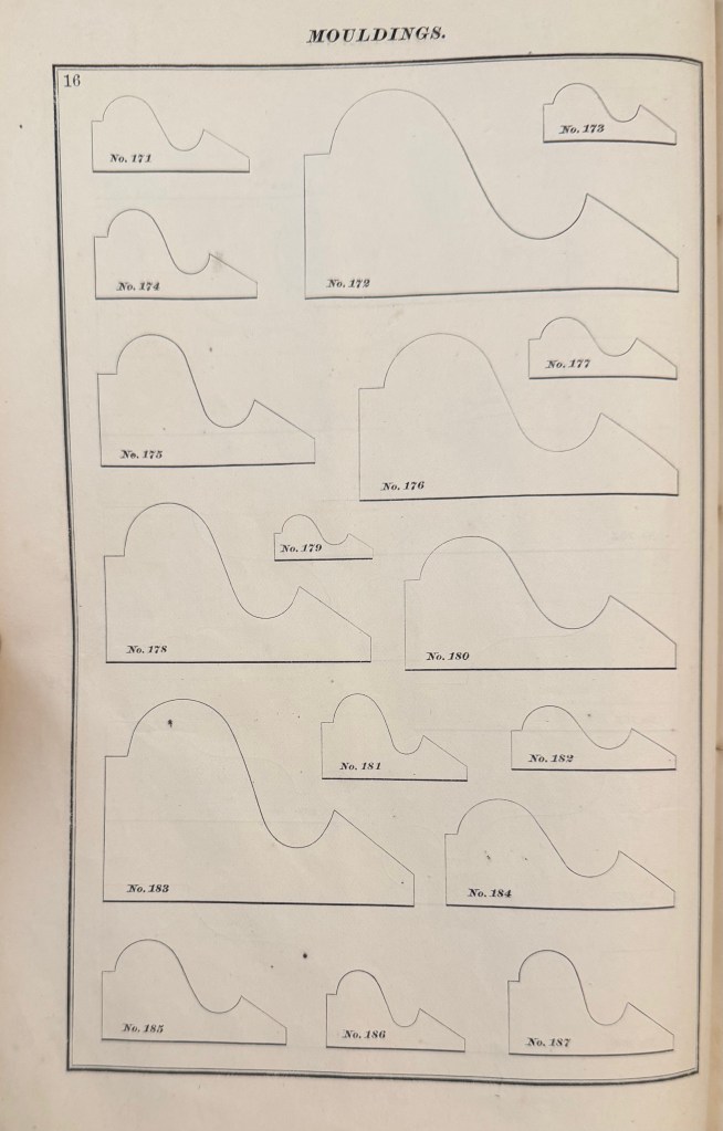
The oldest moulding catalogue that I own is the Universal Moulding Book from 1874. This catalogue shows over 650 moulding profiles in full size. It isn’t the first version. I know this because the catalogue states that 46 profiles have been phased out from a previous catalogue.

Here is a page of a profile known as a Quirked Greek Ogee and Bevel, a popular profile in the mid 19th century. Notice that there are 17 different sizes.

Why so many sizes?

Originally moulding or architectural enrichment wasn’t an afterthought. The mouldings were designed to be used in proportion to the openings that they surrounded.

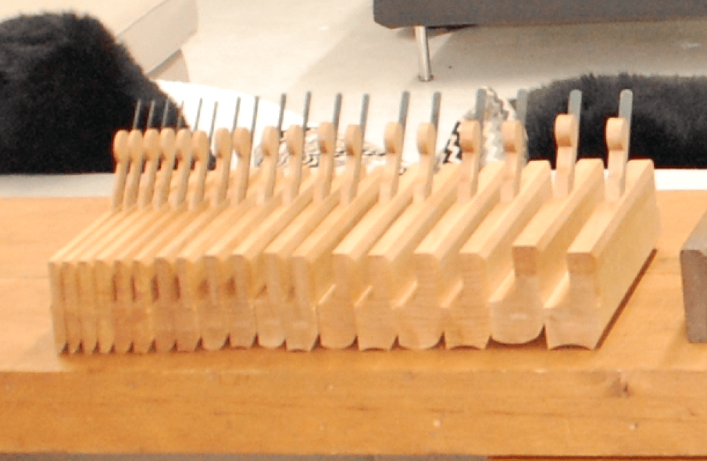
In America, and England, before the Industrial Revolution, wood mouldings were made by hand. (plaster ornament was as well). With a set of planes called Hollows and Rounds, an infinite variety of moulding profiles could be created. A set of planes were designed to created 1/6th diameter arcs in increments of 1/16th inch.

My working set of hollows and rounds

Various pattern books of the period laid out the formulas for creating the mouldings according to the width of the openings. In his 1827 version of Builder’s Companion, Asher Benjamin wrote that for a door or window, the proper proportion would be found by dividing the opening into eight parts and giving one to the width of the moulding, He noted that this formula would provide a different width for different widths of doors and windows, but said that it wasn’t good to have different widths of architraves in the same room.

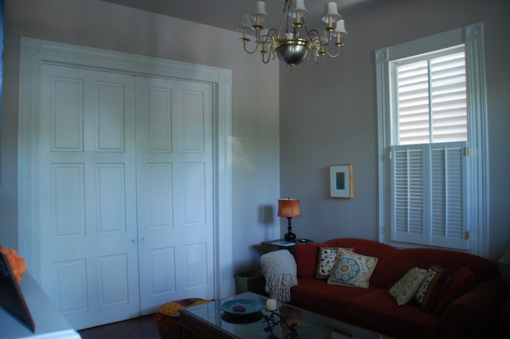
Obviously he wasn’t around to comment on this house interior……….

1839 New Orleans 4-bay townhouse

The pocket door opening in the photo is 6′ wide while the window width is about 3′ wide. You probably don’t notice that the architraves and the corner blocks are different sizes. The casing aound the doos is about 6″ in width while the window casing is less than 5″. The casing that frames the doors would look too large around the windows while the window casing width would be too diminished by the pocket door opening width.

Because the casing widths conform to the opening sizes, they look similar enough in size for their differences to be hard to recognize. The fact that they have proportional details within the overal common profile helps as well.

When the factory-made millworker begain to replace the on-site handmade moulding, they settled on a series of profile sizes that would fit most situations based on common door and window opening sizes.

This variety of sizes began to diminish into the 20th century until around 1940, when most catalogues began to offer only a few or even just one size of each profile.

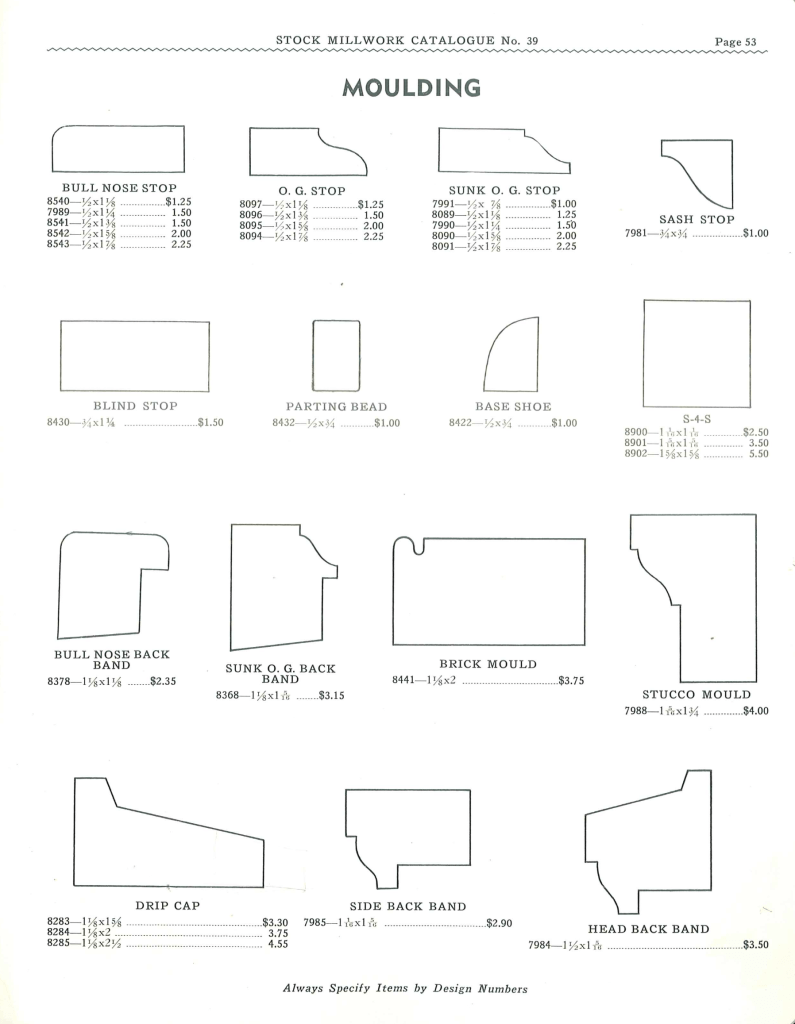
A page from the 1939 Stock Millwork Catalogue

When you have a design that requires moulding profiles that aren’t available, (which is a common problem with 19th century Victorian designs), and you aren’t able to create a built-up moulding from available profiles, you may have to have a set of custom knifes made.

If you order enough linear feet of the mould, some shops will waive the knife fee as it adds to their selection of profiles. Be sure you look into custom knifes before you discount it as being too expensive. The job is also done by CNC now rather than hand-grinding. so the actual operation is not a bid deal.

Moulding In The Classical Tradition Lecture – February 26

If you are in the Los Angeles area at the end of February, The Southern California chapter of the ICAA (Institute of Classical Architecture and Art) is presenting a lecture entitled “Authenticity & Historic Design in Architectural Millwork” on February 26, from 6:00 to 8:00 PM.

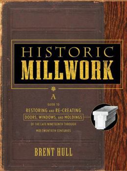
The presenter will be Brent Hull, a nationally recognized expert on historic design and architectural authenticity. He will present information and inspiration from his new book “The Design and Manufacturing of Historic Millwork From 1740-1950” published by Wiley & Sons. 2025.

Hull is an award-winning master builder and expert in historically accurate architectural millwork and mouldings. For over thirty years his craftsmanship has enhanced nationally registered properties and homes across the country. Hull honed his expertise at Boston’s North Bennet Street School where he trained in the art of traditional building and historic preservation prior to founding Hull Millwork & Hull Homes in Fort Worth, Texas.

He has authored five books on historic millwork and architectural design including his most recent work, which is a follow-up to his previous book, “Historic Millwork”, published in 2003. His current book includes moulding of the mid-18th century and early 19th century periods, which weren’t covered in the earlier volume.

He will be talking about the stylistic and functional shifts that accompanied the transition from pre-industrial hand-crafted techniques to mechanized production. Hull provides a framework for identifying period-specific profiles and understanding the design logic that shaped moulding development across two centuries of American building tradition. Participants will gain practical knowledge for making informed specification decisions for restoration and classical new build projects.

Here is the link to register:

https://www.classicist.org/calendar/events/authenticity-and-historic-design-in-architectural-millwork-with-brent-hull

If you aren’t familiar with the ICAA, they are a great resource for connecting with architects and artists who are interested in and trained in the classical arts tradition, both in restoration work and new construction that honors the early periods. They have active chapters all over the country.

Brent will be giving his presentation iat several other chapters around the country so you might check the ICAA calendar if you don’t live on the west coast.

Here is the link to the main ICAA page to find out more about the organization and learn about events in other parts of the country:

https://www.classicist.org


Arch-Anatomy – Electrical Wood Moulding

This is the second in a series of articles on the anatomy of architecture which focuses on construction details. Many of them are details that are now obsolete because of modern building methods or the evolution of designs due to changing tastes.

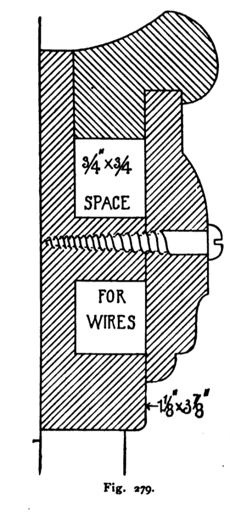
There is a type of moulding available today called ‘electrical molding’ which is either a formed sheet metal channel or plastic channel that is designed to hide electrical wiring on the inside surface of a wall. This simplifies electrifying a room when new outlets are needed or a new light fixture needs to be installed without cutting into a finished wall surface.

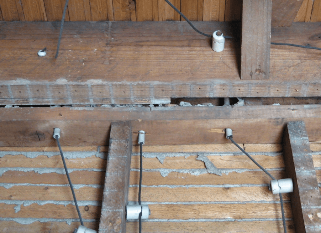
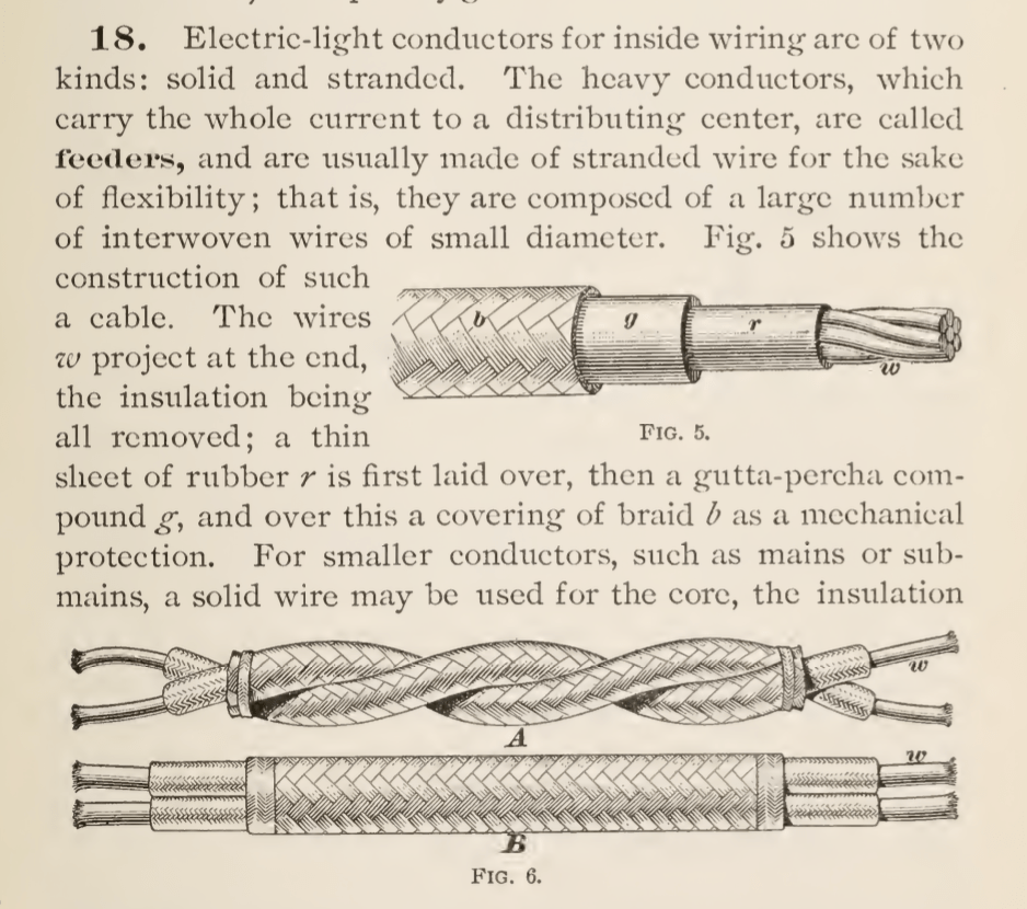
In the late 1800’s the electrification of offices and homes was becoming more popular and the current method of wiring buildings posed a problem. The method at the time was known as ‘knob and tube’. Copper wires which were covered with a rubberized fabric were strung along the unfinished side of walls, underneath floors, or on attic joists and held off the wood surface by attaching them to a line of ceramic knobs which were nailed to the wood studs. When the wiring had to pass through a stud or joist, a hole was drilled and the hole was filled with a ceramic tube for the wires to pass through.

Knob and tube wiring – photo-Laura Scudder
Diagram of typical wiring showing rubberized cloth covering

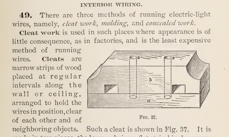
The problem came when the wiring had to run inside a room interior. A cosmetic solution had to be created to hide electrical, telephone, and telegraph lines from view.

A wooden cleat to be used instead of ceramic knobs.

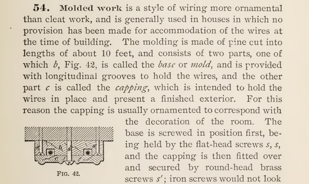
Cutting into the three-coat plaster and wood lath walls of the period to bury wiring inside them wasn’t an easy option when electrifying previously built houses. Early builders manuals suggested designs that hid the wiring inside moulding on the walls. Some suggested creating a moulding which hid the wiring at the top of a tall wainscot paneled wall, or to create a wide picture rail to serve the purpose.

An example of electrical moulding disguised as a wide picture rail.
Another example of a suggested electrical moulding capped by a picture rail mould.

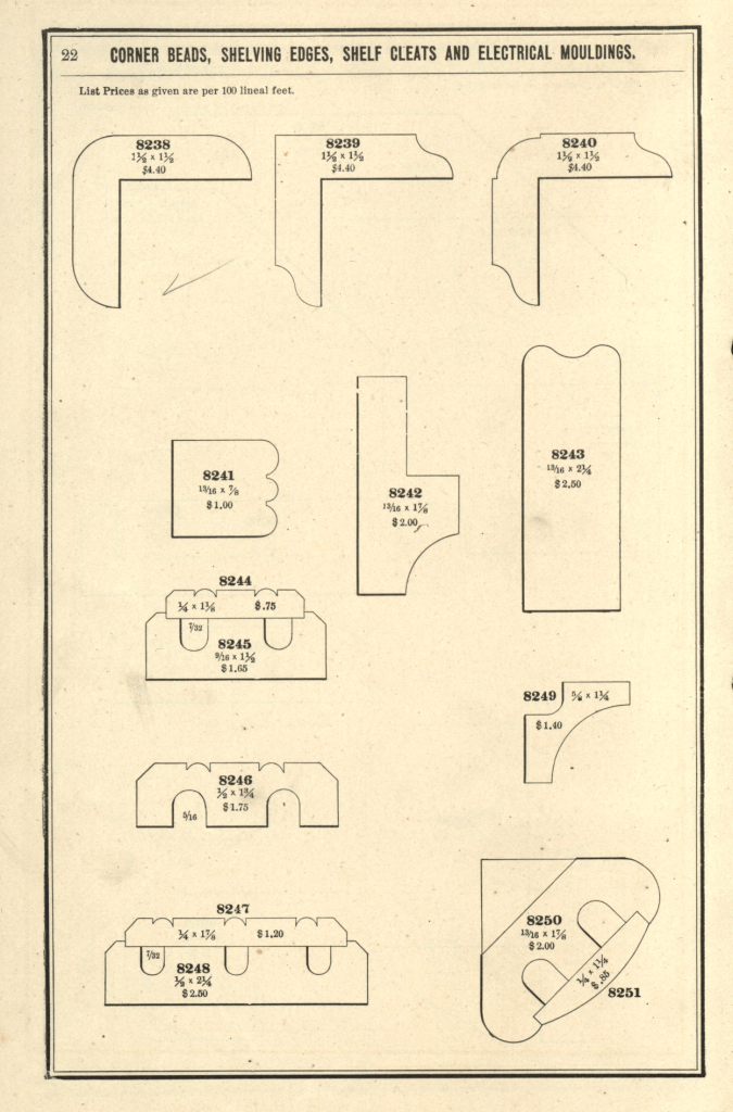
Electrical moulding doesn’t show up in a lot of the moulding catalogues from the period, but a number of them are represented in the Official Moulding Book in their 1907 to 1913 editions.

No. 8249 and 8251 were meant for either a type of cornice mould or to use to run wiring vertically at a room corner.

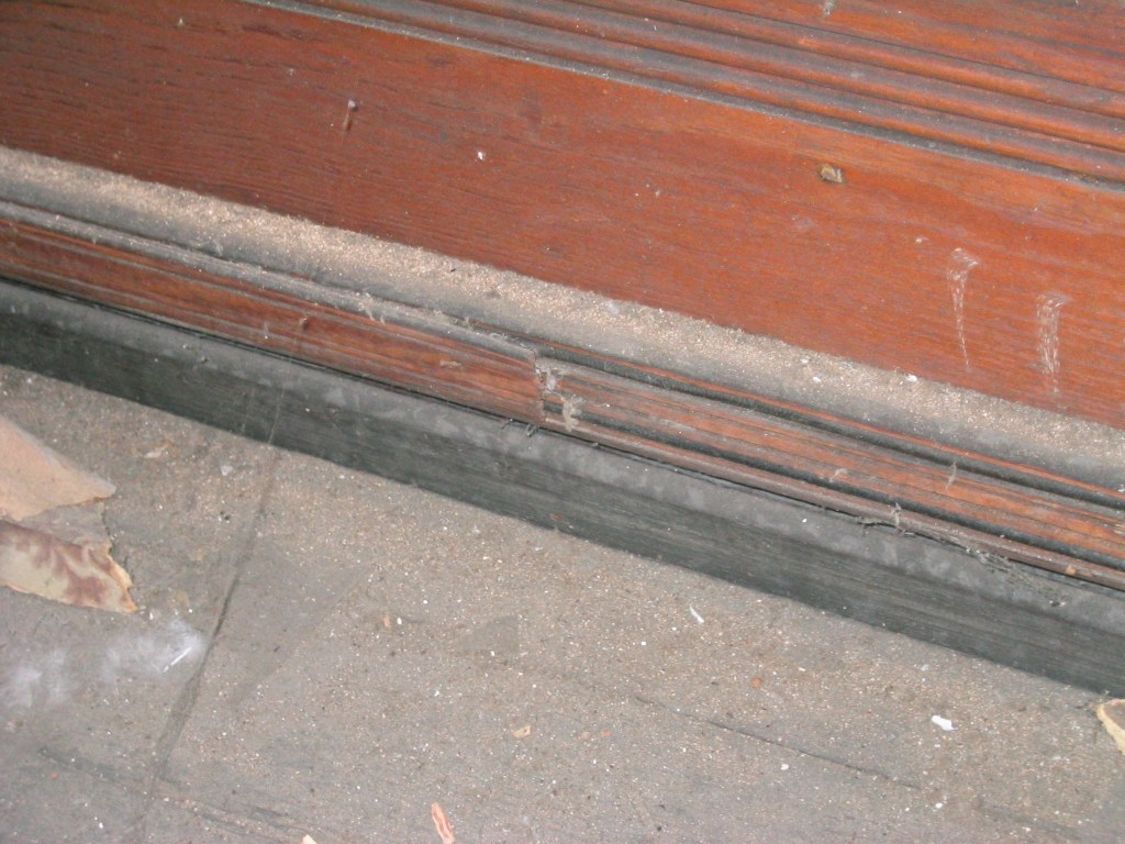
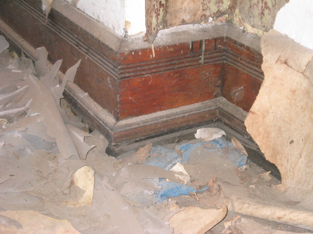
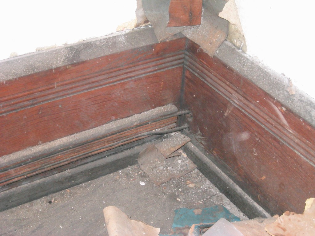
The three photos below are photographs I took inside an 1890 office building before it was renovated. I haven’t been ablr to find this exact mould in any catalogue yet but they are a slightly more decorative version of No. 8244 in the Official Moulding Book.

Photo – R. Wilkins
Photo – R. Wilkins
Photo – R. Wilkins

Note that the wiring runs to the next room through holes in the wall which do not have any insulators. This lack of insulators, the fragile nature of the rubberized fabric coating, and the fact that the wiring was not grounded made for serious fire hazards with the early wiring systems.

Sources:

Official Moulding Book – 1907, The Chicago Millwork and Moulding Co, Chicago, IL

Building Construction and Superitendence, F.E. Kidder, Part II, 1911, William Comstock Co. NY

Cassell’s Carpentry And Joinery, Paul Hasluck, 1908, David McKay Publisher, Phila, PA

Arch-Anatomy – Wood Bricks

This is the first of a series of articles on the anatomy of architecture which focuses on construction details. Many of them are details that are now obsolete because of modern building methods or the evolution of designs due to changing tastes.

(An expanded explanation of an obscure but interesting entry in the Wrand Film Design Glossary.)

If you try to search for ‘wood bricks’ on the internet, you’ll probably come up with some strange answers. They were a standard feature of brick construction in the nineteeth century that went out of fashion for a number of reasons.

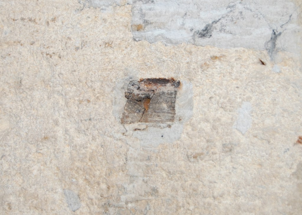
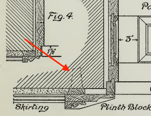
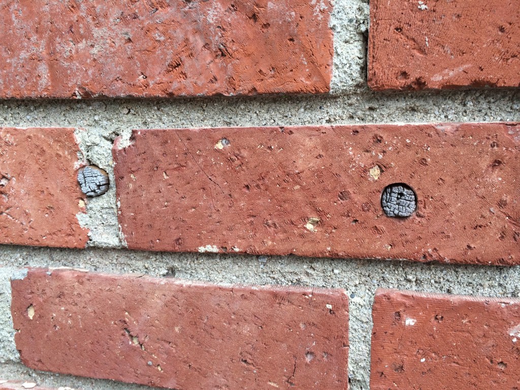
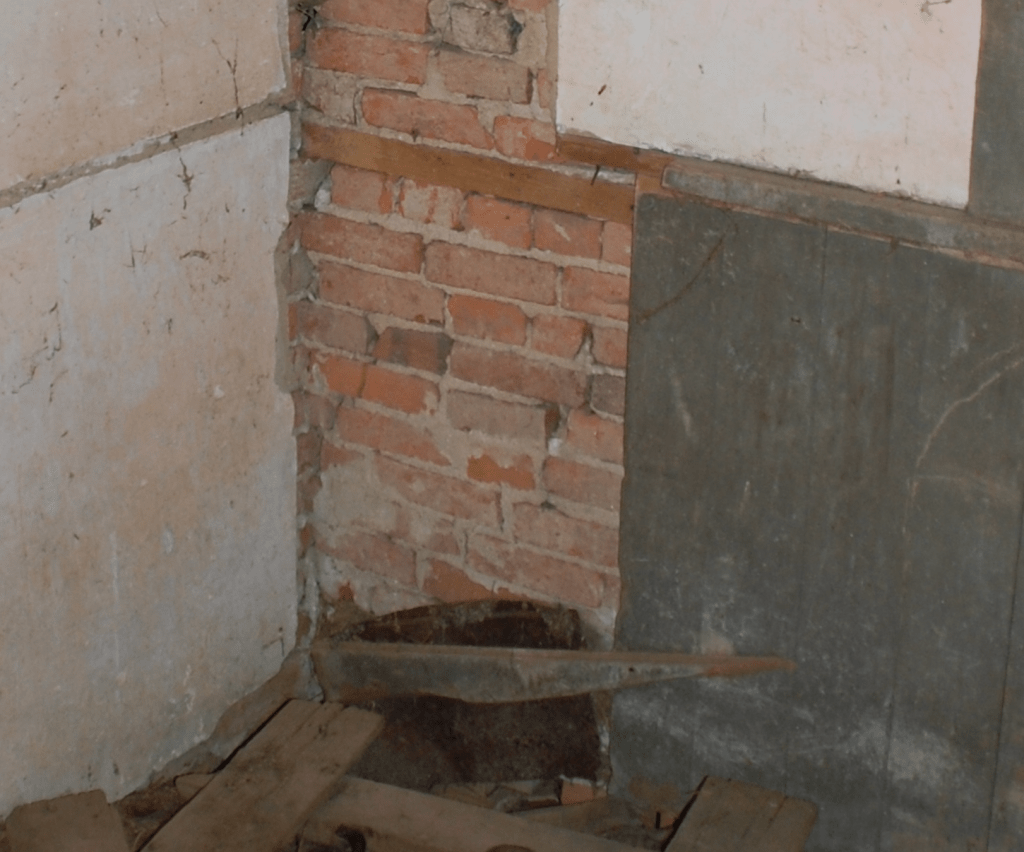
With masonry building construction there has always been the problem of attaching wood elements to stone or brick structures. This was often accomplished by inserting wood plugs into the wall surfaces as an attachment point for nails, or by driving nails into the mortar of joints.

A wood plug in a stone wall of a 17th century Paris hotel.
From a 19th century builders manual showing the use of wood plugs for attaching a door frame.
Wooden plugs in early 20th century brick.

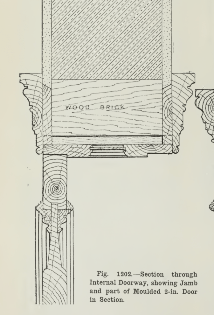
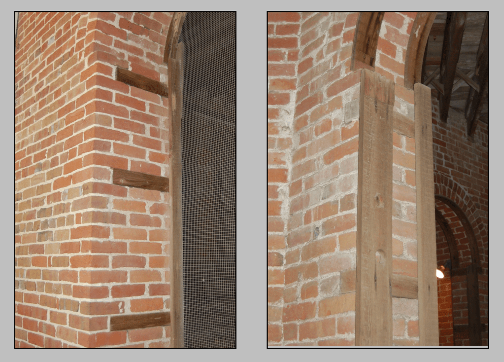
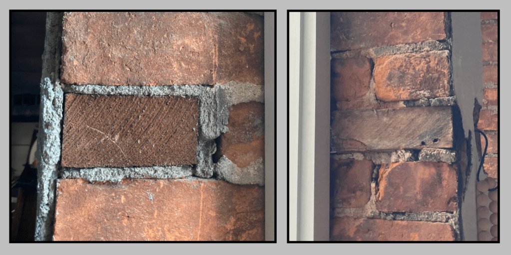
The use of ‘wood bricks’ most likely evolved in England before spreading to America. Most building manuals of the period that mention their use suggest using well-seasoned hardwood billets set between the brick courses at intervals for a way of attaching the wood linings for doorways and window framing.

For narrower wall opening, this lining could consist of a single board like in the illustration below.

Use of a single plank as a door frame lining for a brick wall. Note that the wood bricks are also used to attach the grounds at the door frame for plasterwork. The architrave exhibits typical Neo-colonial profiles, while the bolection mould on the doors frame is a mould typical of Greek Revival houses, a quirked Greek ogee and bevel combined with a fillet and cove, topped with an astragal, fillet, and cove.

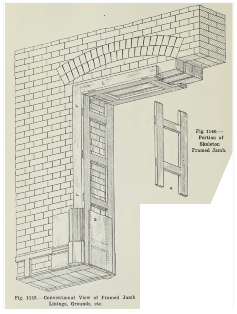
For larger openings in thicker walls, the wood bricks were made longer and the linings were made of several pieces of sawn and planed boards, assembled in what was called a skeleton framed jamb.

The skeleton frame is attached to the wood bricks as well as the wood lintel.

Early manuals show this framework to be mortised and tenoned similar to a frame for furniture, but some mid-ninteeth century examples in America have been observed to be simple vertical boards nailed to the wood bricks rather than a M&T frame. This method would have definitely cut down on the construction time.

The image on the left shows the wood bricks in place while the image on the right shows the vertical boards nailed to them to act as the arch frame lining. Notice the archway lining at the top with boards that have been kerfed at regular intervals to allow the wood to form to the brick archway without having to steam bend them.

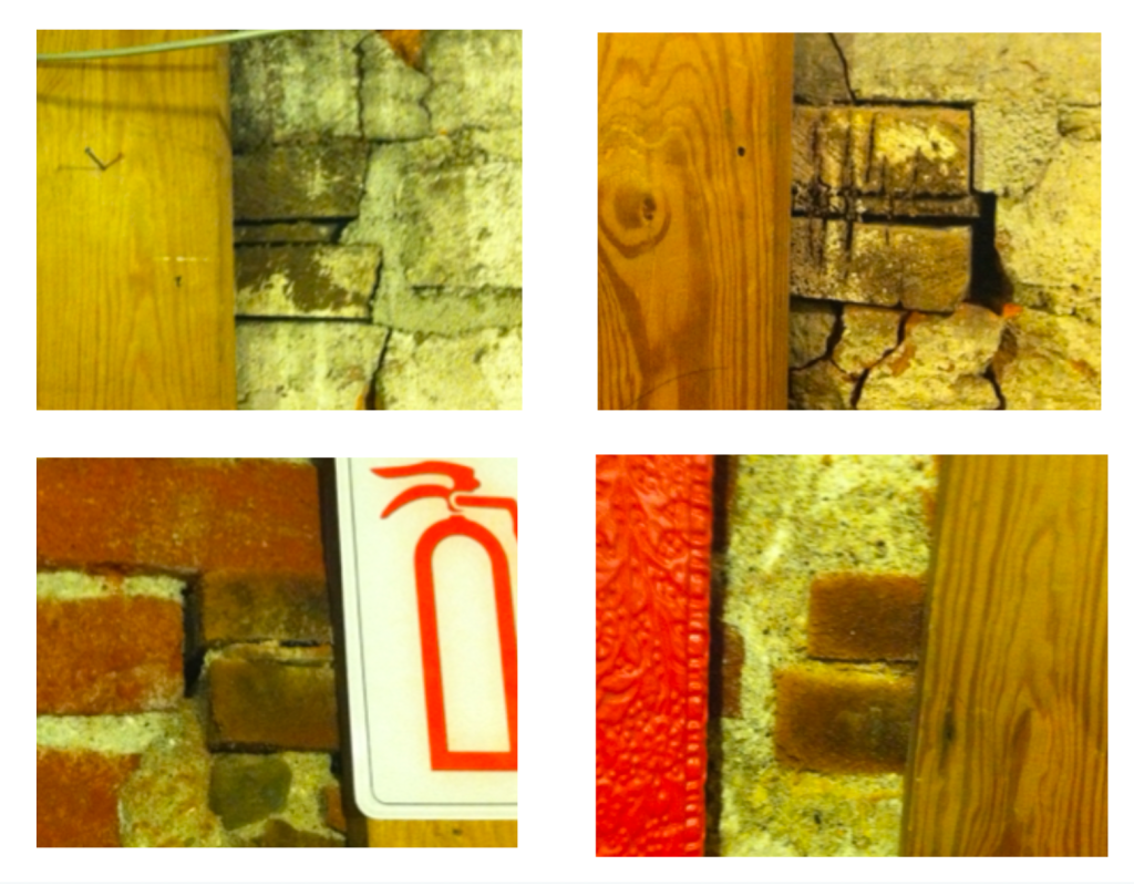
Some turn-of-the-century buildings display a more haphazard approach to wood bricks where framing cut offs of softwood were used instead of hardwood, as in the photos below.

Softwood framing cut-offs used in place of hardwood.
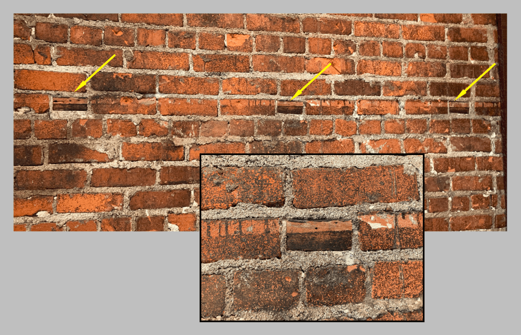
From an early 20th century building in Southern California. Wood bricks are set at 4′ from the floor. Most likely for a wanescot and chair rail.
Long strips of wood inserted in the brick for attaching a paneled wall detail in a 1870’s rural school house.
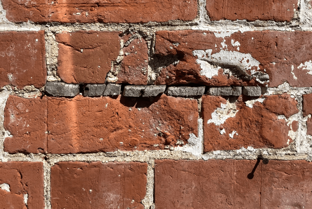
Two more examples of what appears to be framing lumber used as wood bricks.
Pieces of what seems to be lath for plaster inserted into the mortar joints between bricks as an attachment point.
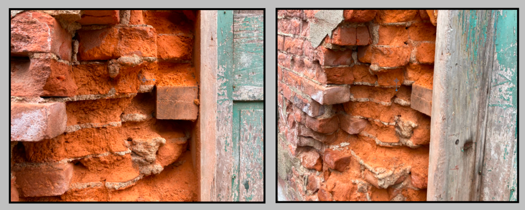
An unusual sight I found on a building in the Mid-west. The exterior brick wall has eroded to the point that the wood bricks of a door frame have been exposed to the outside.

What Is A “Double Dap” Hinge?

One of the reasons that I wrote the Wrand Film Glossary was to record many of the obscure film and entertainment industry terms that get passes down orally but are never recorded.

Art department and set construction lingo is usually not included in the typical film glossary, and “Double dap” is one of those odd terms that you will hear used by Prop Makers* but have probably never had it explained.

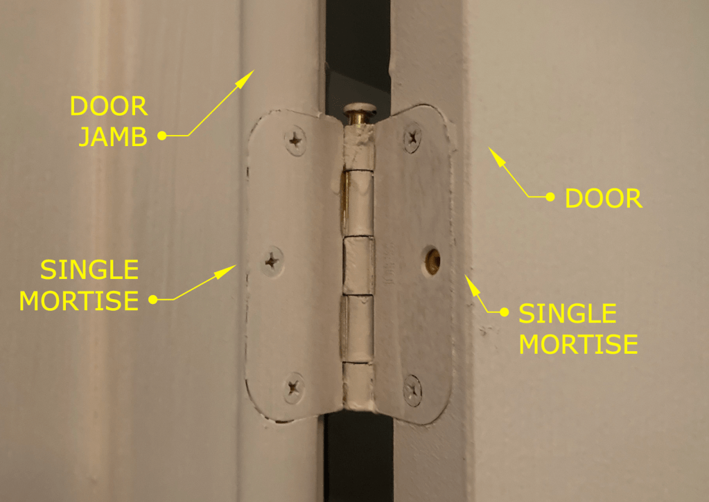
The term refers to how the hinges of a door on a stage set are to be installed. Normally the installation of hinges for a door involves creating mortises in the door stile and the jamb that match the thickness of the hinge leaves. That’s referred to as a “single dap” installation. (Note: this is specifically for doors in North America or the UK. Many Continental European doors are half-overlay and don’t use the type of leaf hinges that are standard here.)

Typical hinge installation – referred to as a Single Dap

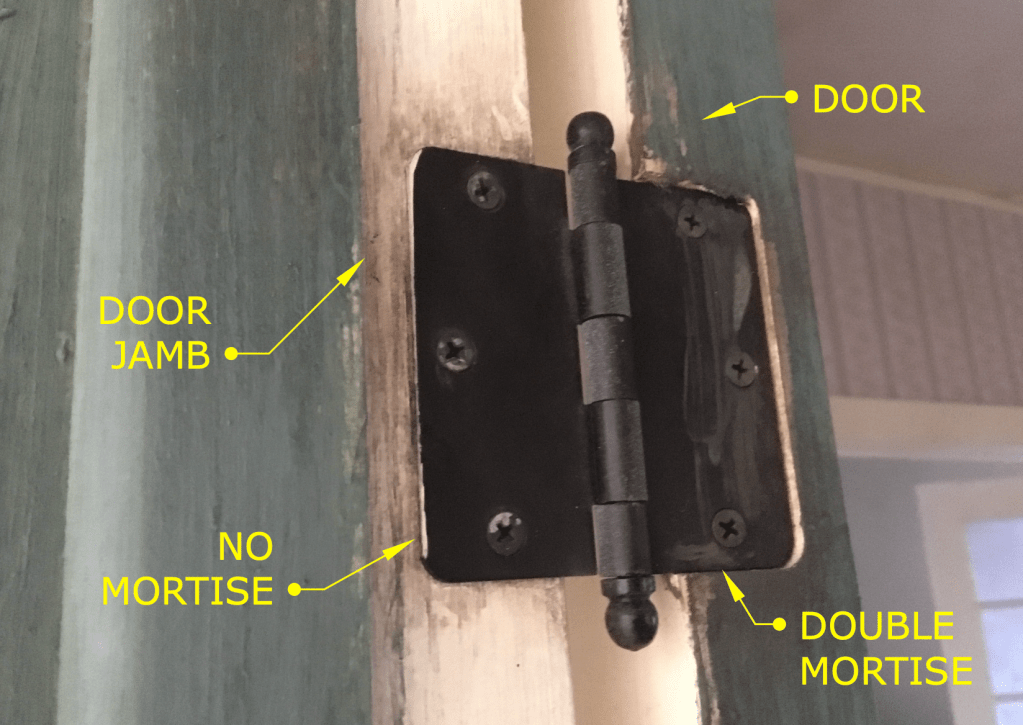
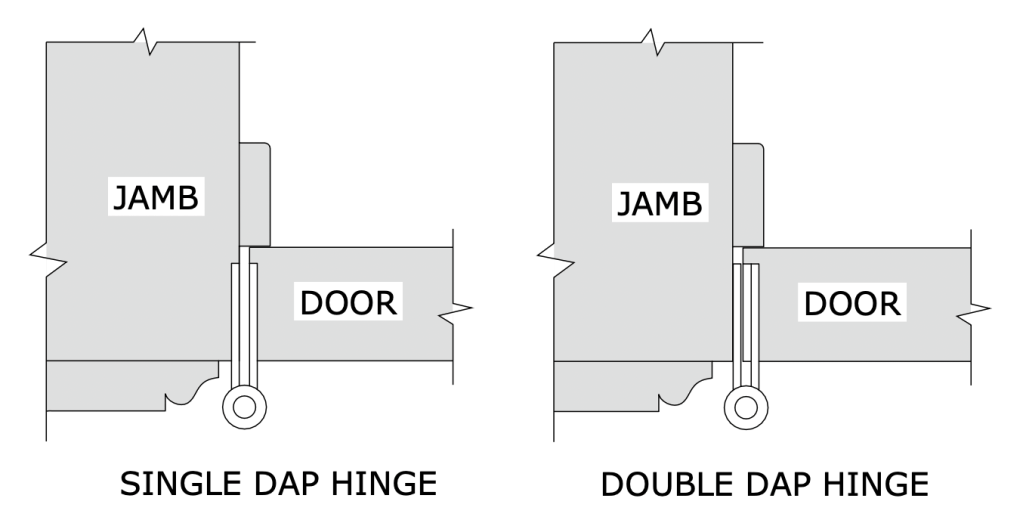
A “double dap” installation involves creating a mortise in the door which is twice as deep as usual and not making a mortise in the jamb, as shown below.

Example of a Double Dapped hinge

The diagram below is a side-by-side plan view showing both types of installation.

So what’s the purpose of this? Well, this is something that is more typical on sets for a broadcast show than on sets for a feature film.

One advantage is speed. We tend to build sets at a pretty brisk pace, sometimes building an entire set over a weekend. For example, if you have a set with six doors, that means you need to install 18 hinges, which means routing 32 mortises. With a double dap installation you cut that number in half.

Another advantage is if you are redressing a set and need to change out the door of an opening for a different door. With a standard installation, you will need to patch and fill and re-rout three mortises. Instead you just need to fill some screw holes.

This is also the case if you need to change the swing direction of a door at the last moment. (Good luck prying off and repositioning that door stop.)

Double dapping has fallen out of favor lately. Production Designers don’t like the look of it for one thing. (Along with Phillips head screws on a period hinge!) They tend to stick out particularly when the hinges are a contrasting color from the jamb or if the wood is painted a light color and the hinges have a dark laquer/black finish. In some instances this condition can either visually hide the extra mortise depth or accentuate it.

Also, notice the round corners on the hinges in the photos. Round corner hinges are a 20th century invention to speed up production. Once machinery, i.e. routers, was being used for mortising, it became a lot faster to create hinges with leaves that didn’t require squaring off the mortise corners as was necessary for period, square hinges. Round corner hinges come in 1/4″ and 5/8″ radius corners, so be aware of what radius size they are if you’re choosing hinges for a door that has already been mortised.

Note: Prop Maker is a designation for a union stage carpenter in Los Angeles to differentiate them from a ‘civilian’ carpenter. They are trained it building theatrical scenery of all types and historical periods and specialize in creating scenery for film productions. They are more similar to cabinet makers than a typical carpenter and are skilled in construction techniques and methods that would baffle most people outside the entertainment industry.

The Art Of Technical Drawings

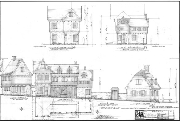
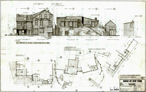
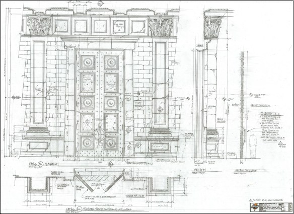
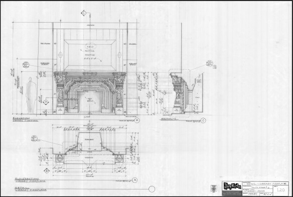
The look of construction drawings for film and television has changed a lot over the years, particularly now that most drawings are done digitally with computers rather than by hand.

While many current drawing styles now incorporate photo-textures, shadows, and icons to add life to drawings beyond what is typical of architectural drawings, it’s hard for them to match the aesthetics of hand drawings.

CAD drawing from 3D model – photo textures applied

Having started as a pencil draftsman I guess I do have a bit of a personal bias, but the unique style of each person on a hand-drafted drawing was immediately recognizable to people who knew their work.

Before digital illustrations and renders of 3D models, hand-drafted drawings had to serve as a design sales tool as well as instructions for scenery construction.

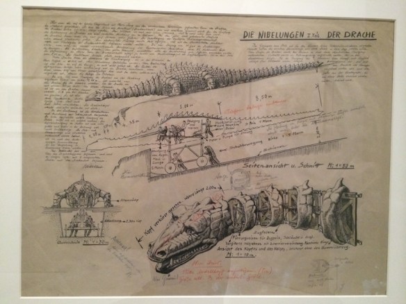
Here are some shots of a set design by Erich Kettlehut in 1923 for the UFA film, Die Nibelungen, for the scene where Siegfried kills the dragon.

The drawing was displayed as part of an exhibition of artwork from the UFA silent film period of the 1920s and 30s at the Los Angeles County Museum of Art in 2014. The drawing is from the collection of La Cinématiquè Française in Paris, France.

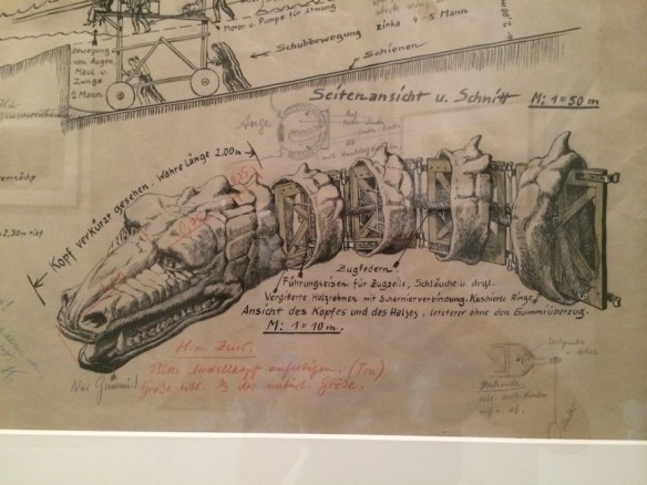
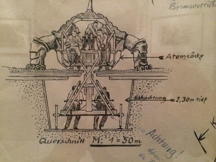
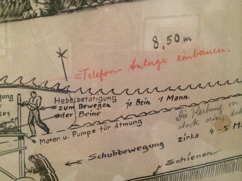
Note that the drawing not only provides a pictorial description of what the dragon should look like, but calls out dimensions, construction materials, how the action prop is to be operated, surrounding scenery requirements, and specific technical details of mechanical movements.

Technical drawing of the Dragon by Art Director Erich Kettelhut – ink and pencil on vellum
Kettelhut called out the length of the neck as well as the tension springs, framework, control cables and hoses required for the creatures fiery breath. He calls out “only rubber!” for the mouth area.
The size and depth of the recessed path required for the props operators.
drawing describing how each part of the dragon was to be operated by stagehands.
Note in red indicates that a telephone/communication system needs to be added to the prop for the crew.

The scene where Siegfried slays the dragon in Die Niebelungen from 1923

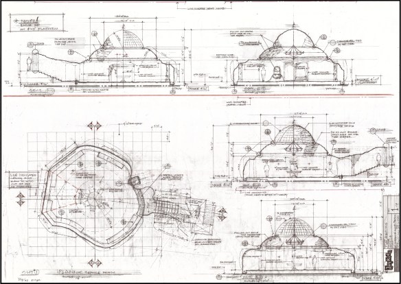
Here are a few more hand-drafted pencil drawings from more recent films:

Salem – drawing by William Ladd Skinner
Gangs Of New York – drawing by Luca Tranchino
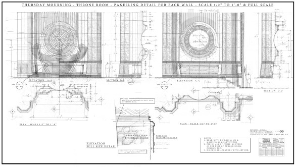
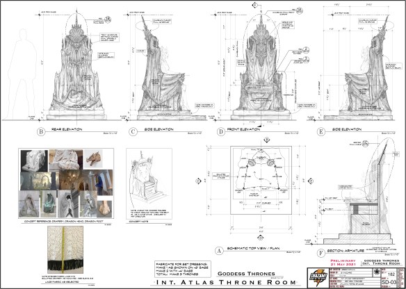
Shazam – drawing by Greg Papalia
Haunted Mansion – drawing by Barbara Mesney
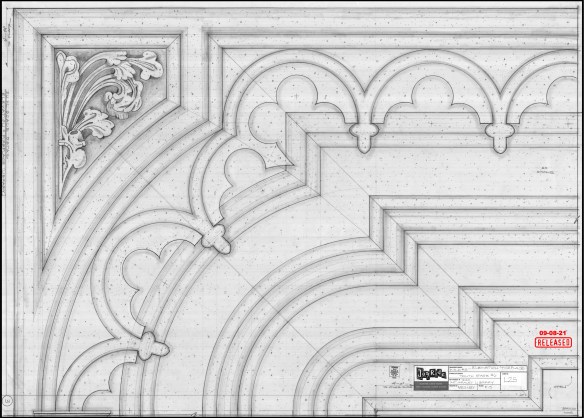
Haunted Mansion – full size detail of fireplace for the plasterers
Thor – drawing by Oli Goodier
Shazam – drawing by Stella Vaccaro
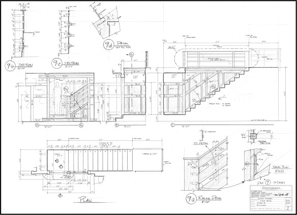
Disturbia – drawing by RD Wilkins
Haunted Mansion – drawing by Hugo Santiago
Baby’s Day Out – window detail

R.D. Wilkins