It’s been 100 years since the start of World War I. On this Armistice Day (Veteran’s Day in the U.S.) it’s a good time to reflect, or learn about the first ‘modern’ war and it’s horrible legacy which still has a hold on us today, as seen in this article in the Telegraph about excavations at the Flander’s battlefield.
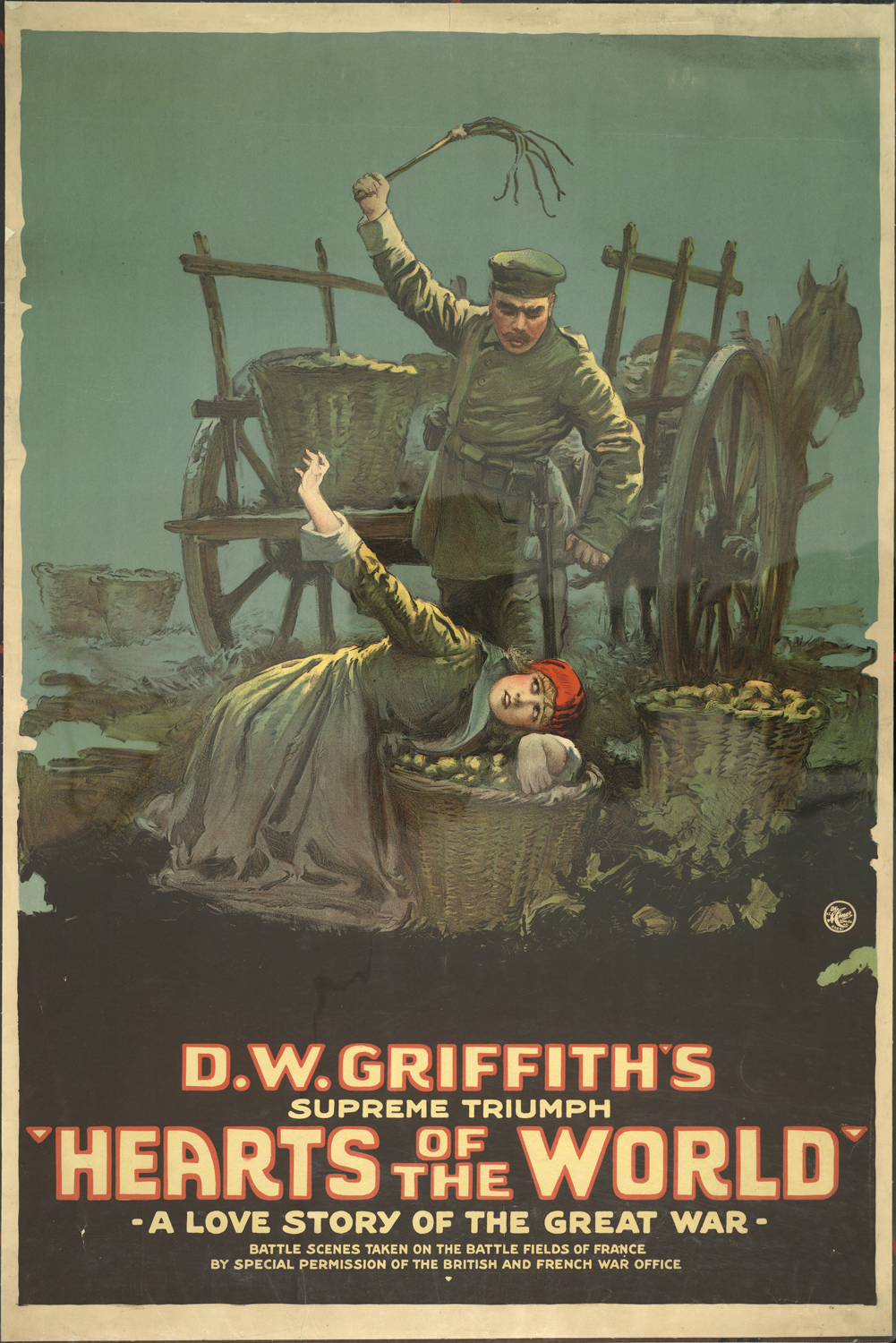
The world’s film industry was quick to turn stories from the war into movies, starting in 1917 when the British government invited D.W. Griffith to come to Europe and gave him access to the from lines where he shot footage for Hearts Of The World, a Paramount picture designed to change American attitudes about the war and encourage the public to push the country to become involved in the war.
Here are a list of my 20 favorite films about the conflict, in the order they were released. They are from different countries and reflect different parts of the war but they all have in common a goal of trying to look at the war from a human level, stripping away the glorified attitudes that started and perpetuated the conflict for 4 years.
J’accuse – France 1919 (director Abel Gance shot footage during the war resulting in realistic and haunting scenes)
The Big Parade – USA 1925
Wings – USA 1927 ( the first film to win an Oscar for Best Picture )
Four Sons – USA 1928
All Quiet On The Western Front – USA 1930
Westfront – Weimar Republic 1930
Niemandsland – Weimar Republic 1930
The Dawn Patrol – USA, 1930
Berge In Flammen – France, Weimar Republic, 1931
Grand Illusion – France 1937
What Price Glory? – USA 1952
Paths Of Glory – USA, 1957
Lawrence Of Arabia – USA, UK 1962
King Of Hearts – France 1962
Oh! What A Lovely War – UK , 1969 ( has an amazing cast)
Johnny Got His Gun – USA, 1971 ( inspired the song “One” by Metallica )
Gallipoli – Australia, 1981
Capitaine Conan – France, 1991
Joyeaux Nöel – USA, France, UK, Germany, Romania, 2005
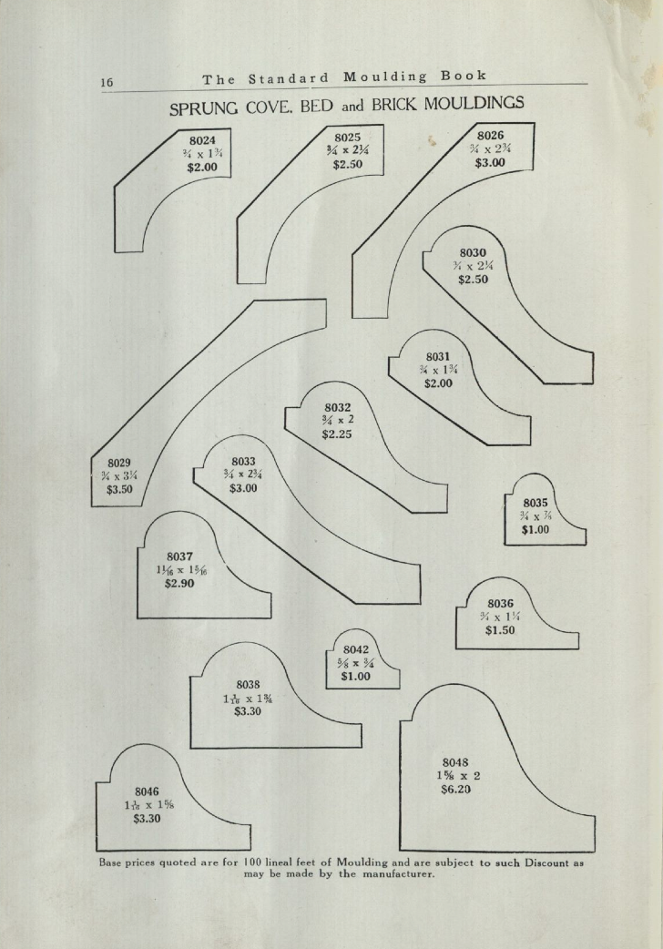
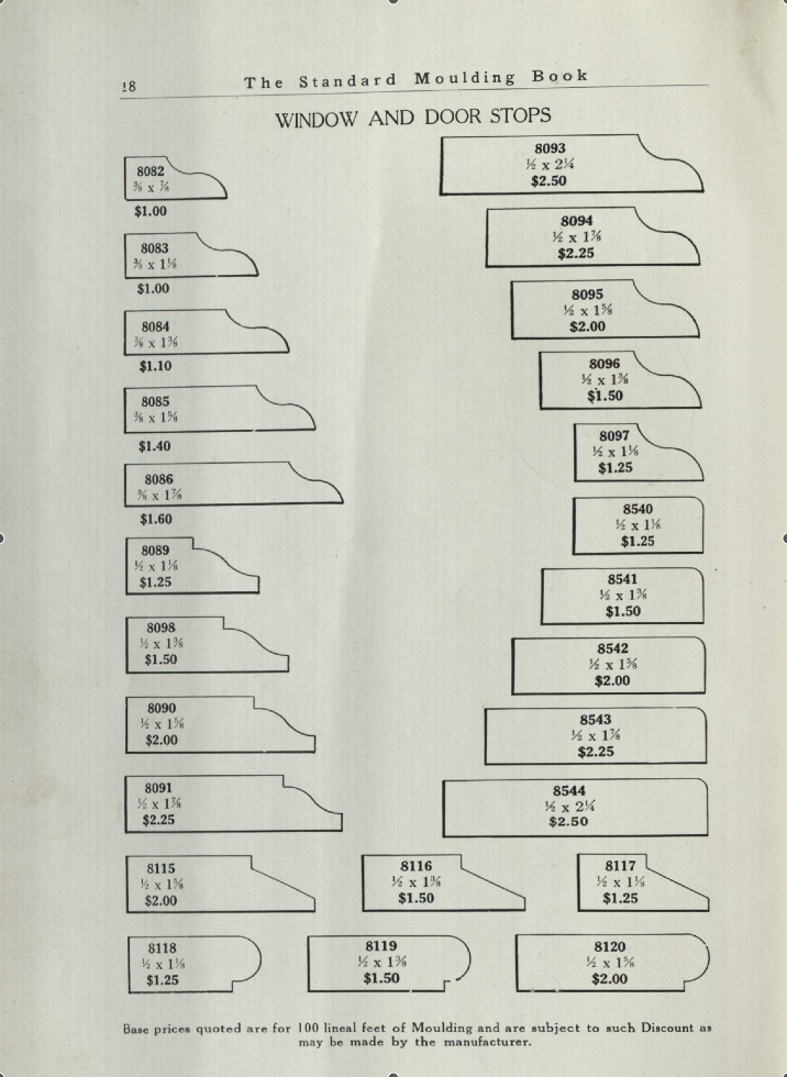
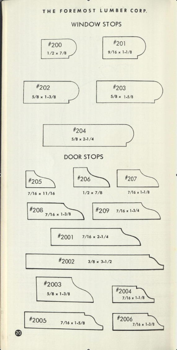
Chris Schwarz over at Lost Art Press posted a blog entry yesterday with links to three moulding catalogues you can download. The catalogues range from a 1938 catalogue using the old Universal system where the profile numbers were a fairly universal ( at least within the U.S.) numbering system called the 8000 system. The original numbering system begun in the mid 1800’s used a three digit number starting with 1. You can see how the inventory of stock moulds changed over the years as manufacturers offered fewer and fewer profiles. The mid 1800’s catalogues included over 600 different profiles which would dwindle to less than 50 in many catalogues in the early 1950’s.
Here’s three examples that show the slow loss of the variety of stock stop moulds, the first from the 1890’s catalogue, the second from a 1938 catalogue and the last from a booklet from the 1960’s.
stops from the 1890 Universal catalogue
Stop profiles from a 1938 catalogue
stop profiles from a 1960’s catalogue
You can read the blog article and download the catalogues at this link. Special thanks to Chris, Eric Brown and Thor Mikesell for sharing the research material.
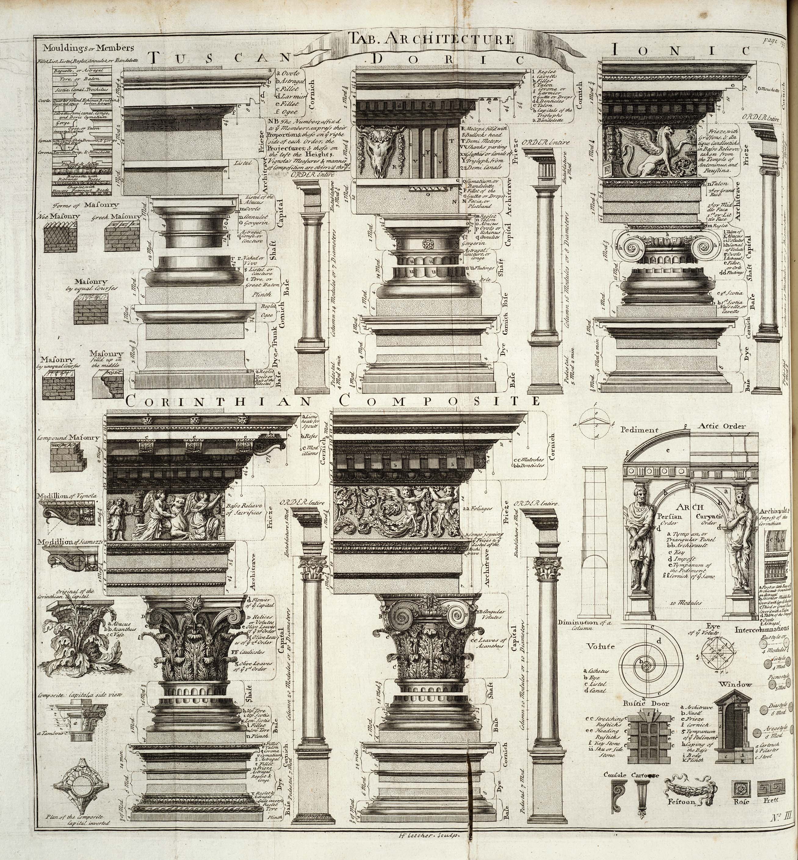
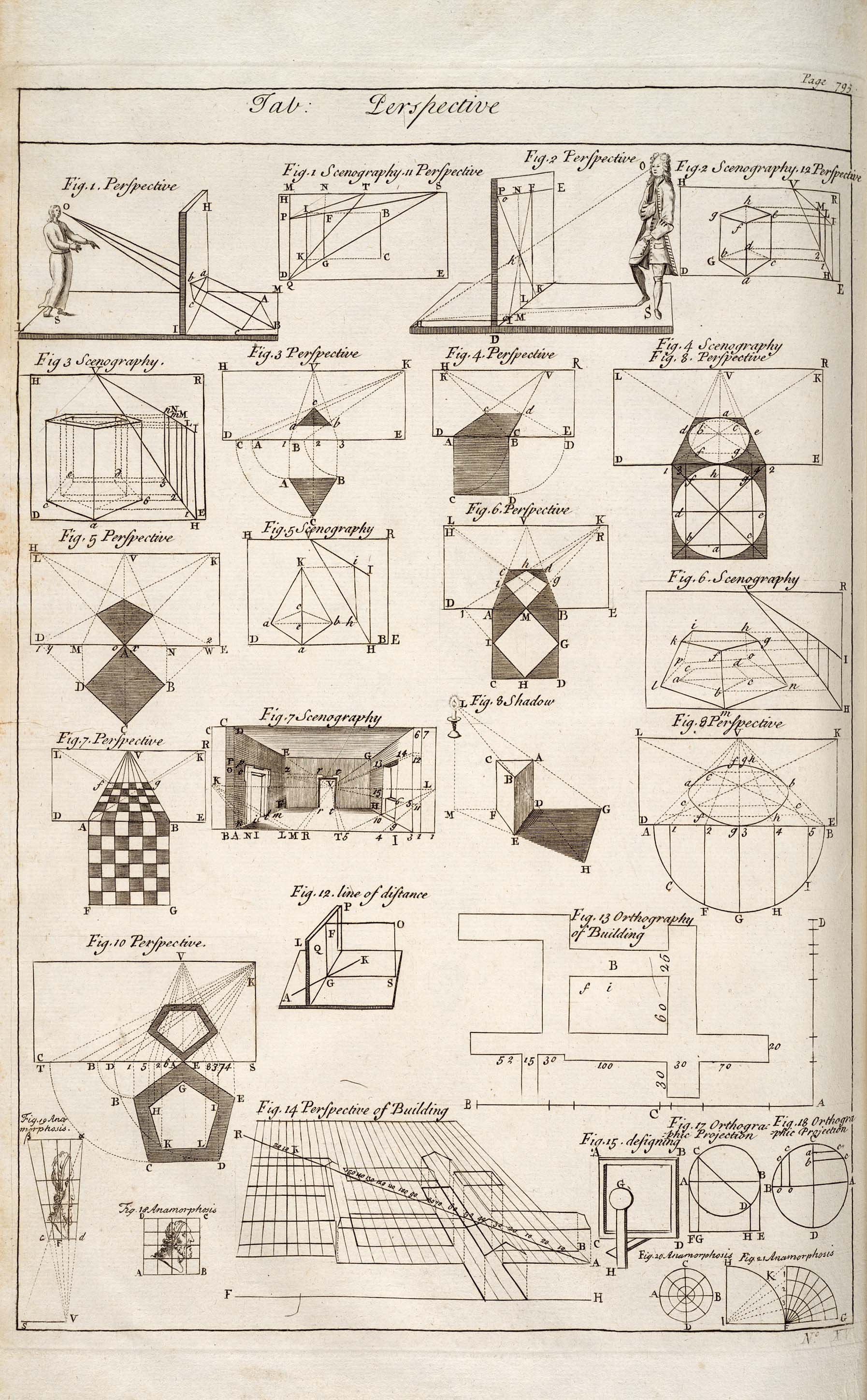
“Cyclopaedia, or, an Universal Dictionary of Arts and Sciences: Containing the Definitions of the Terms, and Accounts of the Things Signify’d Thereby, in the Several Arts, both Liberal and Mechanical, and the Several Sciences, Human and Divine: the Figures, Kinds, Properties, Productions, Preparations, and Uses, of Things Natural and Artificial; the Rise, Progress, and State of Things Ecclesiastical, Civil, Military, and Commercial: with the Several Systems, Sects, Opinions, etc; among Philosophers, Divines, Mathematicians, Physicians, Antiquaries, Criticks, etc.: The Whole Intended as a Course of Ancient and Modern Learning.”
Fellow Set Designer Scott Schneider alerted me to two reference sites that are a real treasure trove of images. The University of Wisconsin has recently digitized an original 1728 edition of Ephraim Chambers’ Cyclopaedia. They have done an excellent job of creating high quality scans of the plates that have always been hard to read in older scans.
You can find the link to the scans here. I’ve posted the scans of some of my favorites below.
Scott also drew my attention to a great site for period photos and drawings at:
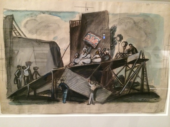
At the Los Angeles County Museum Of Art now until April is a special exhibition of artwork and posters from the German Expressionist period of the silent film era, 1919 to the mid 1930’s. Produced in association with La Cinémathèque Française and the Academy Of Motion Picture Arts And Sciences, the show features over 150 pieces of artwork from classic films of the German UFA studio.
Along with many posters are a large number of original set and costume design drawings which are seen together for the first time here. Most of which have not been on display here before and others only seen as small images in publications.
Of course artwork from the most well-known films are there; The Cabinet Of Dr. Caligari, Metropolis, The Nibelungen, but there are many others from more obscure films as well including Robert Hearlth’s original schematic of the forced perspective backings from Der Letzte Mann which were such a sensation.
One of Ernst Stern’s drawings for Waxworks, which indicates the set design, platforming, camera position and lighting.
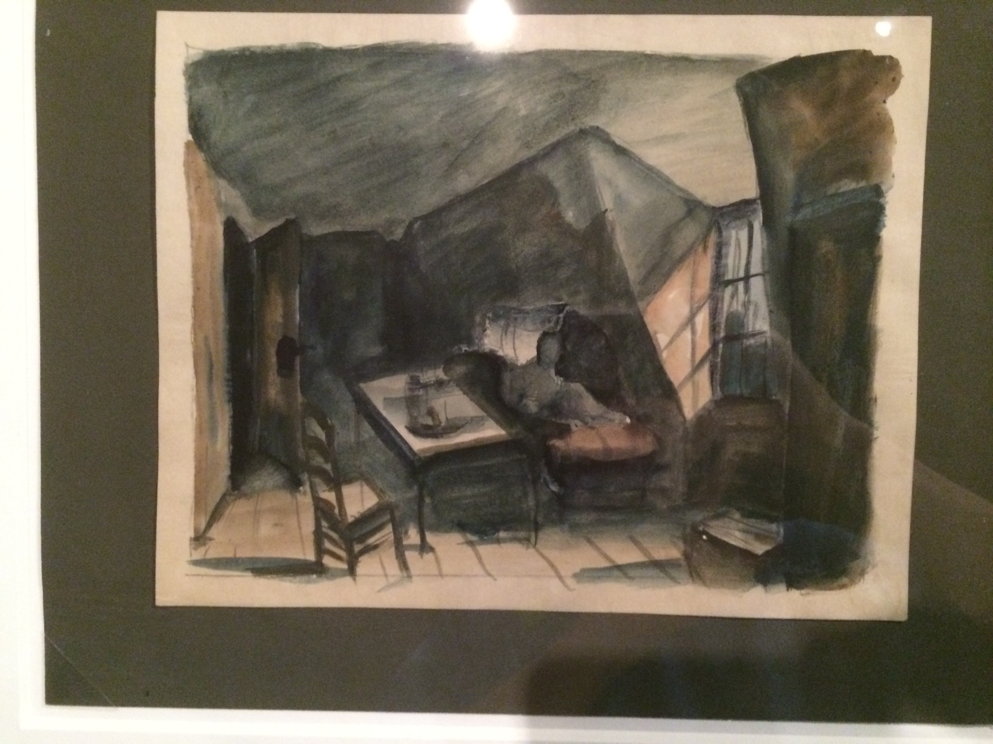
A watercolor and charcoal drawing for one of the sets for Dr. Caligari by Walter Röhrig
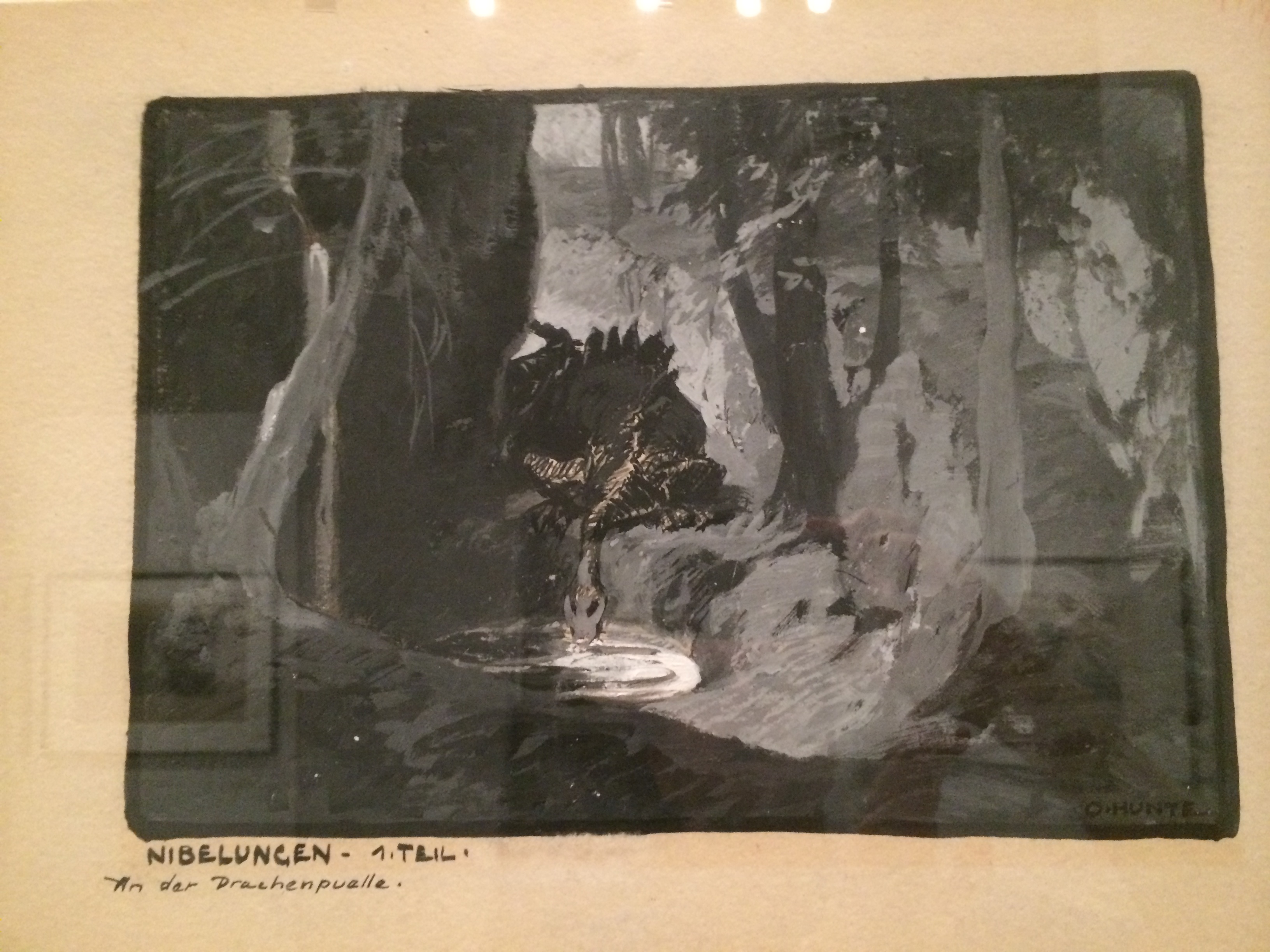
It was common during this period of German cinema for Art Directors to work in teams of two or three people, dividing the design duties among themselves as matched their individual abilities. A perfect example of this is the work of Otto Hunte and Erich Kettelhut on Fritz Lang’s The Nibelungen. Here is a drawing by Hunte of the dragon by the waterfall.
Gouache painting of the dragon for Die Nibelungen by Otto Hunte.
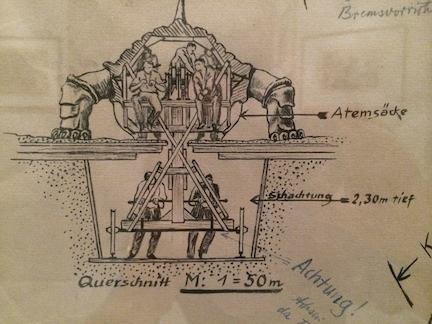
Being the more technically trained, Kettelhut elaborated on the design by drawing the technical requirements of the dragon to carry out the action called out in the script.
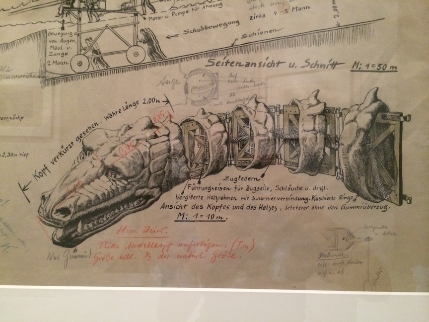
Technical drawing of the Dragon by Erich Kettelhut
Kettelhut carefully described how the giant action prop was to be built and operated both with stage requirements as well as the on-board personnel’s responsibilities.
Enlargement of Kettelhut’s drawing describing how each part of the dragon was to be operated by stagehands.
The size and depth of the recessed path required for the props operators.
Kettelhut called out the length of the neck as well as the eye detail, tension springs, framework, control cables and hoses required for the creatures fiery breath. He calls out “only rubber!” for the mouth area.
Here is the scene from the film where Siegfried finds and kills the dragon. The effect is quite crude by our modern film standards but must have been thrilling for a public new to such spectacles. Imagine the lot of the half dozen stagehands stuck inside the big, airless prop as it bellows smoke from inside it. Notice the large forest and mountain sets created for the film, truly epic efforts for the time.
The title ends in a question mark because I’m not sure I have a definitive answer yet on my search for the the oldest existing scenery from a film. So, I’m asking everyone out there to help me with this quest.
The stage of the oldest intact film studio in Sweden, and maybe the world. photo by Reinhold Fryksmo
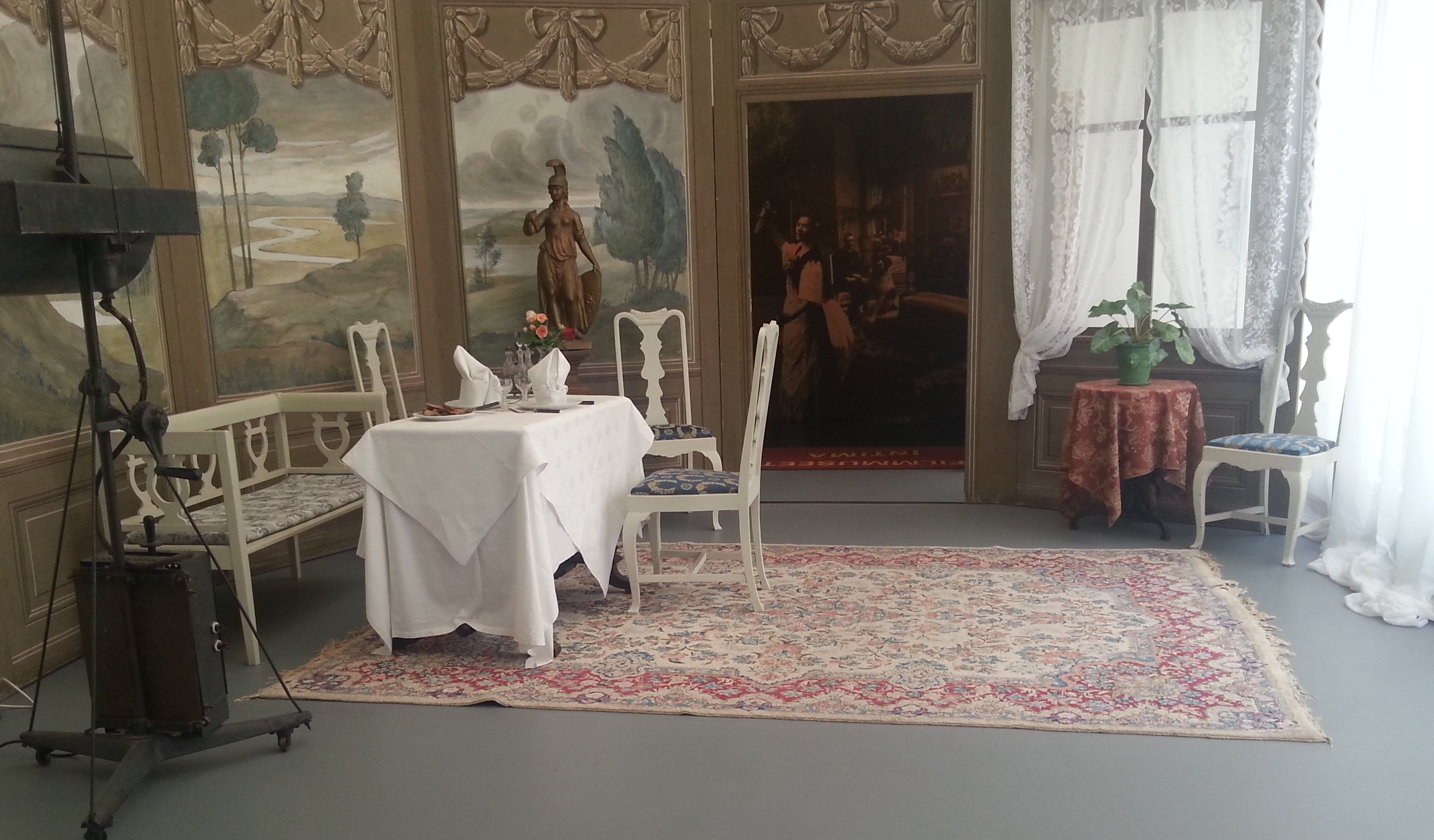
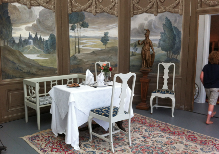
Let’s use this as a starting point: in Kristianstad, Sweden there is what is reported to be the oldest intact film studio from the silent period. Inside the studio museum (Kristianstad Filmmuseet) is a display in what was the original glass-walled studio space. It is dressed as a set from the 1909 film, Fänrik Ståls Sägner, one of three films made at the Kristianstad Biograf-Teater that year. The scenery appeared throughout the film apparently as the same space was used for a number of different scenes. The main element is a multi-panel theatrical style flat painted with a Trompe-l’œil design. If this is truly the original set piece then this is in excellent condition for a 105 year-old flat.
So is this the oldest film scenery in existence? I’d love to hear from other Art Department people out there from around the world with older examples.
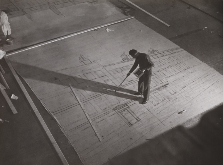
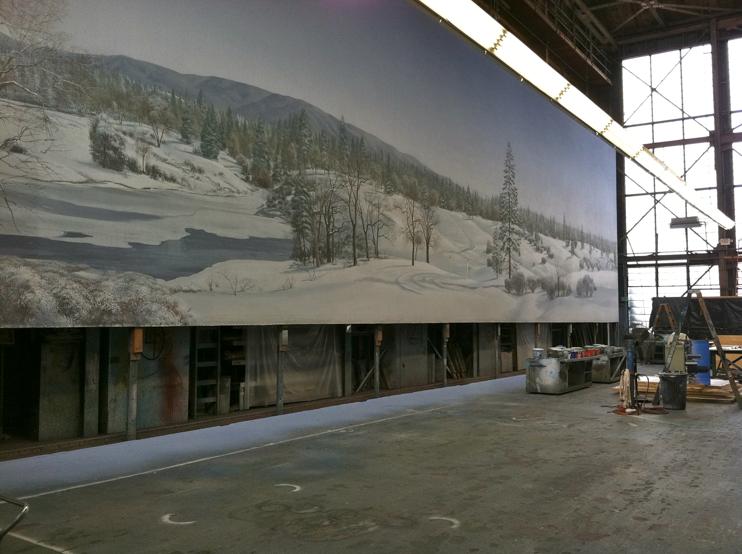
A scenic lays out a backing at Ealing Studios in London in 1939 for the film “Young Man’s Fancy”. National Media Museum
In my last post on painted backings I mentioned that they had some definite advantages over photographic backings but I didn’t go into details.
Here’s some of the things they have in their favor:
1. “Softness” – Painted backings have a much more atmospheric feel to them visually. This could be enhanced by adding a “haze” to the canvas or hanging bobbinette, white or black, in front of them to soften them further. Many cinematographers hated the photographic backings when they were introduced because they were too sharp, which made it hard to try and have believable depth-of-field with a backing that was supposed to imply a distant object.
2. Canvas backings can be enhance with elements to simulate a more realistic setting: L.E.D. or miniature bulbs, cellophane strips that simulate light reflecting off water features, etc. You could do that to a Translite but it’s hard to repair the holes you’ll make in it.
3. Painted backings can be altered easily to reflect changing seasons. You can paint over a backing to create, snow, leaves, remove architectural elements and restore it back to it’s original form where you would need entirely different photographic backings in each case.
4. A painted backing has infinite possibilities, any angle, and location. There’s no need to have to get a camera at the point of view you want the scene to be shot from. No need to worry you’ll get strange perspective lines from a Photoshopped image.
And for those who don’t believe a painted backing could ever look as realistic as a photographic one, I’ll offer up this little story:
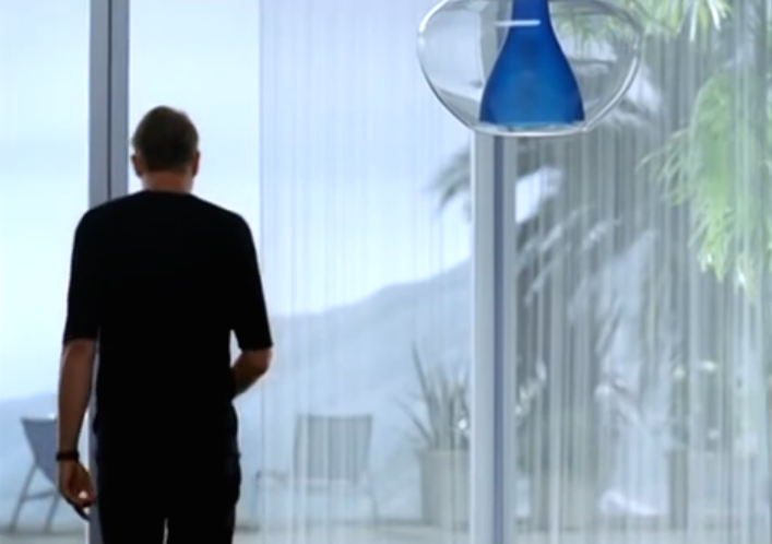
Years ago I was working on a feature that involve a 160′ long backing of a coastline and ocean view. It had to match a location which was a modern house with floor to ceiling glass panels. The designer suggested a painted backing would be better for many reasons.
One of the producers scoffed at the idea saying that since we would see so much of the backing he couldn’t believe it would look realistic enough. Because the painted backing was actually going to be cheaper he was overruled on the decision. He would walk on to the stage sometimes while it was being painted and just shake his head. “They’ll be sorry”, he said.
Several weeks later he walked into the Art Department with the writer and walked up to my drafting board, pointing to a photo on the wall of an ocean view, the sun glowed in the background and the light was glinting off the water.
“You see that. That’s what they’re trying to recreate with a painted backing!” he laughed.
I interrupted him. “That is the painted backing. I shot that yesterday after they hung and lit it.” I pointed out a studio light hanging just inside the top of the frame.
He got quiet and leaned in closer, studied the photo, and then just turned and left. He never mentioned it again.
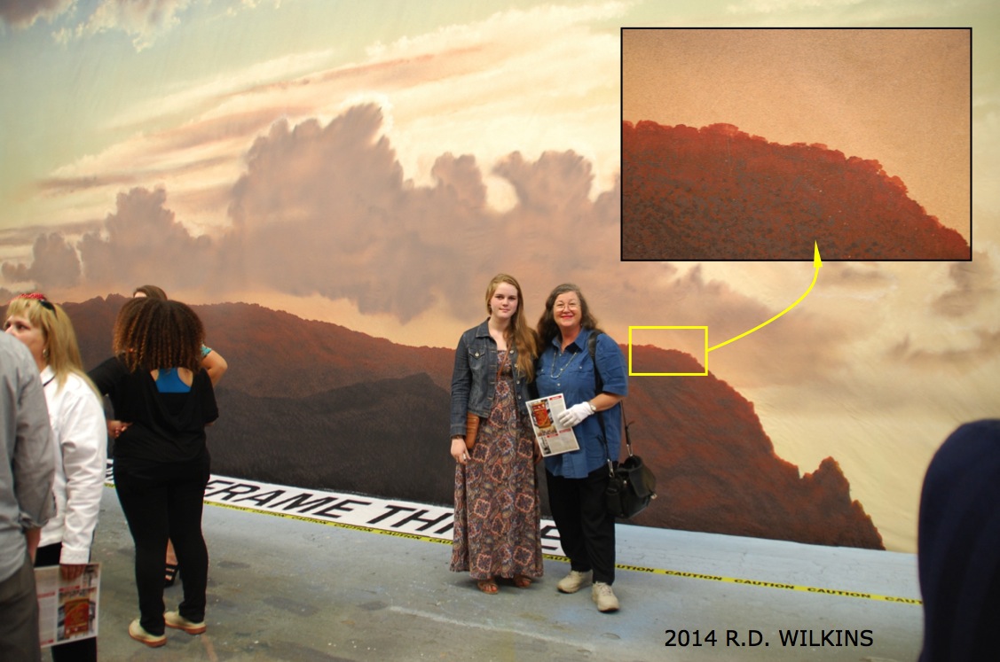
Remember, it doesn’t matter what scenery looks like to your eye. It’s all about how the camera see it.
A painted backing seen outside the set windows
Here are some more photos from the JC Backings / ADG event:
Backing from the film Brigadoon
Backing from the original Battlestar Gallactica TV show
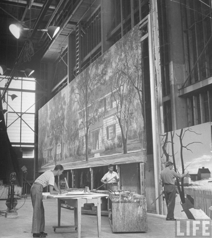
“In 1903, Pathé (the first Pathé studio in Vincennes) had two cameramen [who were] paid 55 francs a week. The designers/painters, much better paid, began at 90 francs a week. A week then was 60 hours and payment was made every Saturday in gold.”
Gaston Dusmenil, Bulletin de l’ A.F.I.T.E.C., no. 16 (1967)
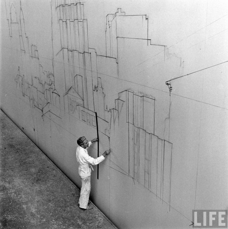
“The scenery [ in early 1900‘s France ] was painted flat, like stage scenery. The canvas (about 20 x 30 feet) was tacked to the floor, and after applying a coat of glue size and whiting, the designer drew the design in charcoal. For complicated architectural sets a small sketch was made and squared for enlargement. Since the size paint was used hot, a scale of grays running from black to white was prepared in advance in small flameproof buckets. The scene painter worked standing, walking on the canvas (in rope shoes or socks) and using very long-handles brushes: straight lines were drawn with the aid of a long flat ruler, similarly attached to a handle. To judge the whole, in order to accentuate effects if needed or to remove unnecessary details, the artist had to mount a ladder. The completed canvases were attached either to wooden frames to form flats, or else, to vertical poles so they could be rolled up.”
Léon Barsacq, Caligari’s Cabinet and Other Grand Illusions
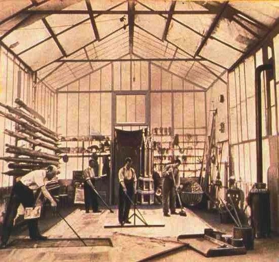
Mèliés’ Montreuil Studio
Painted backings have been a staple of filmwork since the very beginning. Georges Méliès was the first to recognixe the possiblilites of incorporating painted backings in his films which he realized could be a vehicle for creating a dramatic narrative and not just for recording real-life as the first short films had.
Even today, with the current trend of green screens and digital effects, audiences are often unaware that the view outside the windows of a set are actually hand-painted backings. While photographic backings, basically photographic images greatly enlarged and printed on heavy mylar or polyester fabric, are the norm in backings these days, the painted backing still has not only a definite place but even distinct advantages over their photographic competitor.
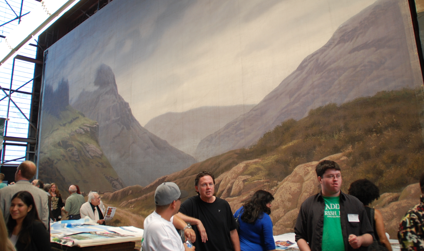
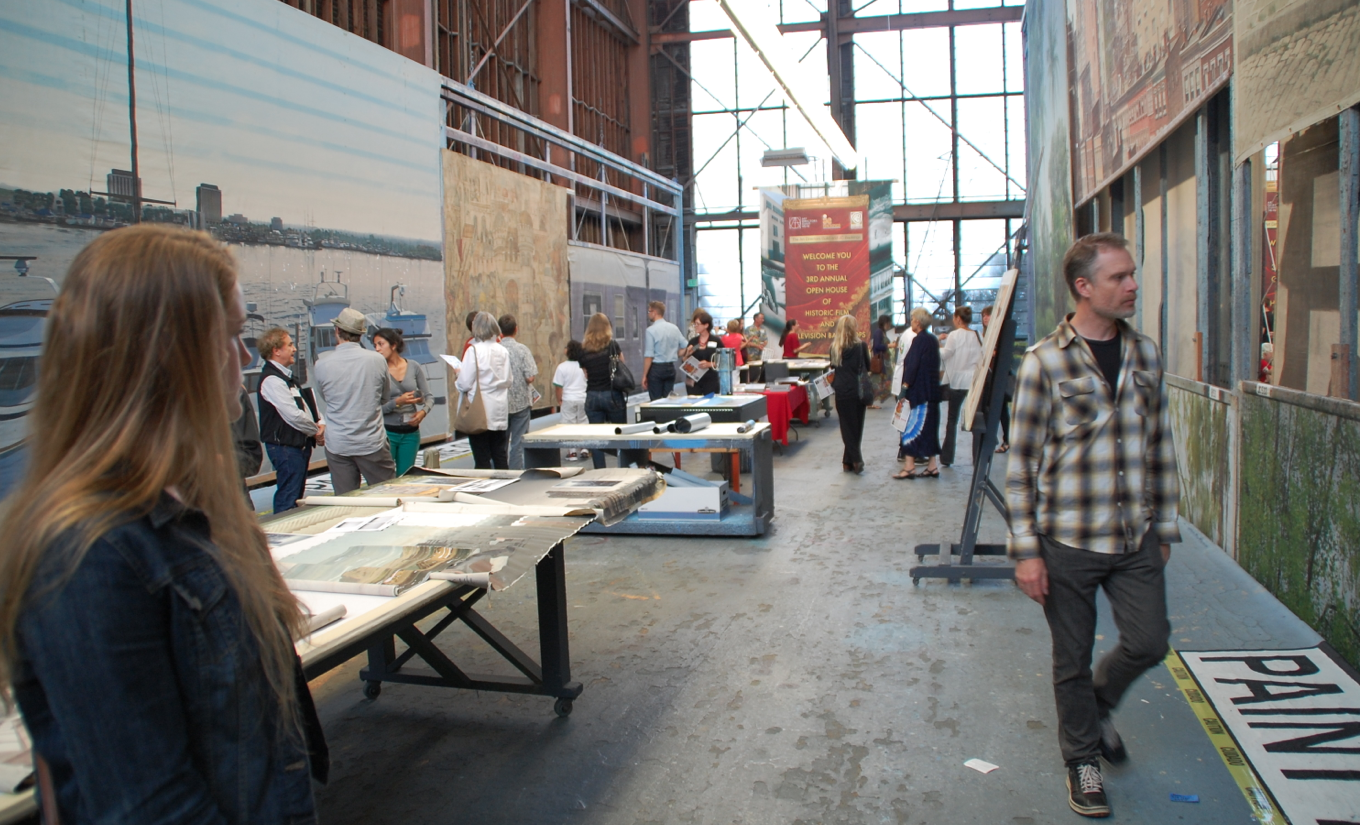
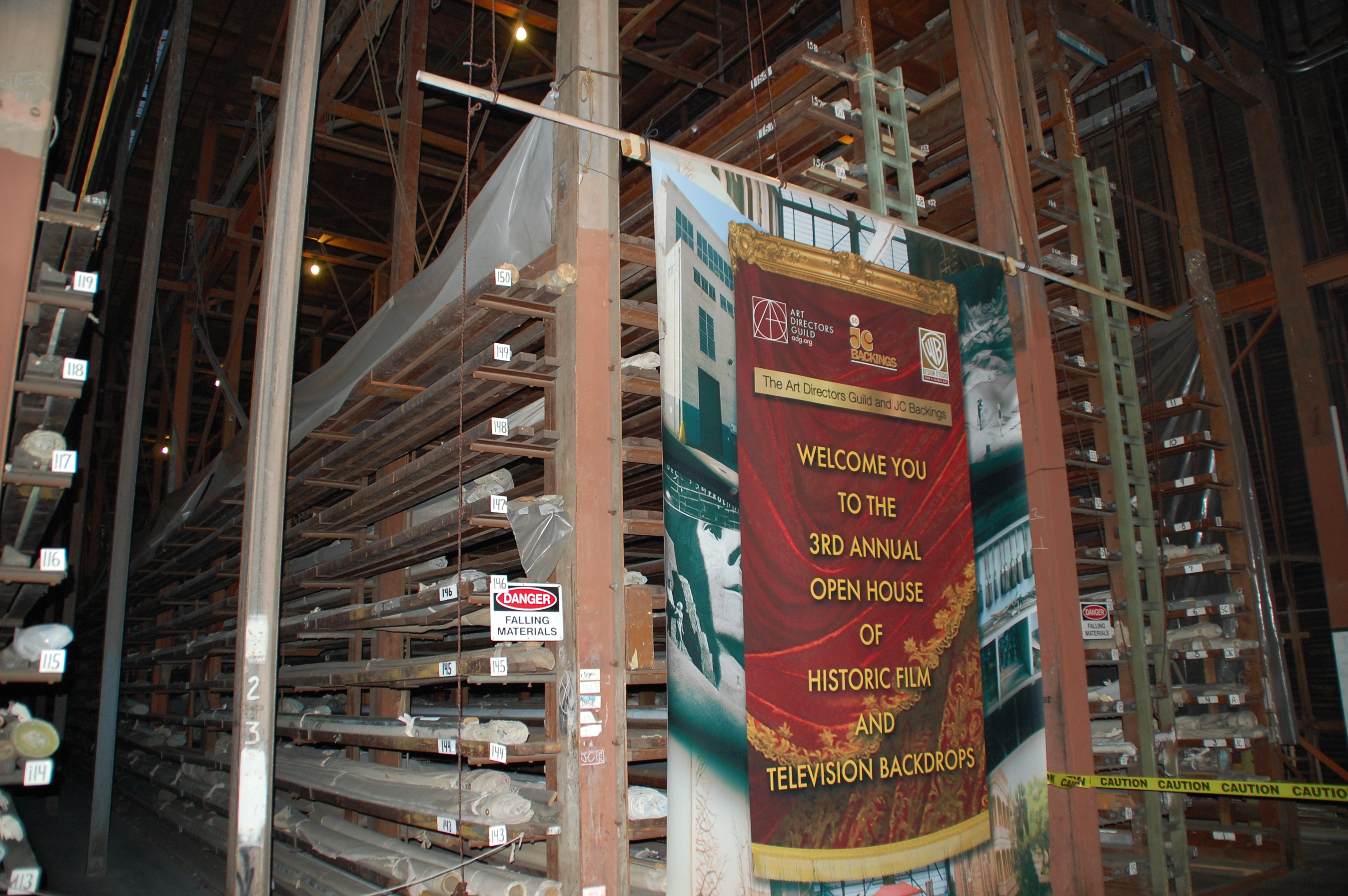
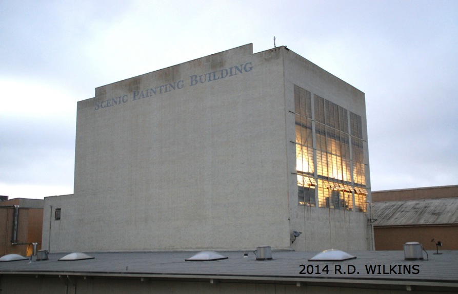
J. C. Backings, who make their home in the historic Scenic Painting Building on the old MGM lot in Culver City (now Sony Studio) recently hosted a Historic Backings event along with the Art Directors Guild here in Los Angeles. They pulled a number of backings from their collection of over 5000 backings, along with several from the Warner Bros. collection and displayed them on the six paint frames where the backings were painted originally.
The storage racks for backings at J.C. Backings
Along with the backings were displayed a collection of smaller scale studies, paint notes, research photographs and examples of the backing design process as well as numerous photos of backings from their archives.
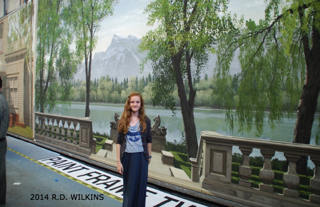
Usually only seen in partial focus and in the background, it’s wonderful how realistic most of these backings are even when seen up close and out of context.
The Scenic Painting Building on the Sony Lot (formerly MGM)
Backing from The Sound Of Music
Backing from South Pacific. Notice the inset close-up of the brush work
Sample of photo reference for a backing along with notes and a small preliminary paint study for the final backing
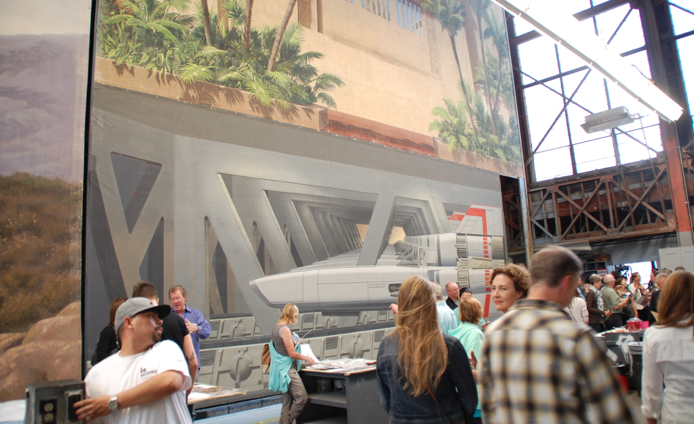
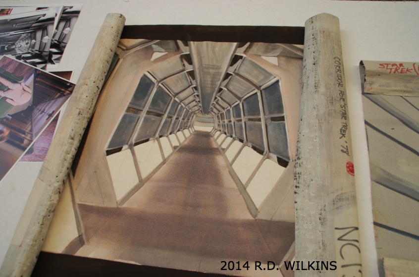
small painted comp for a backing for a corridor of the first Star Trek film in 1978
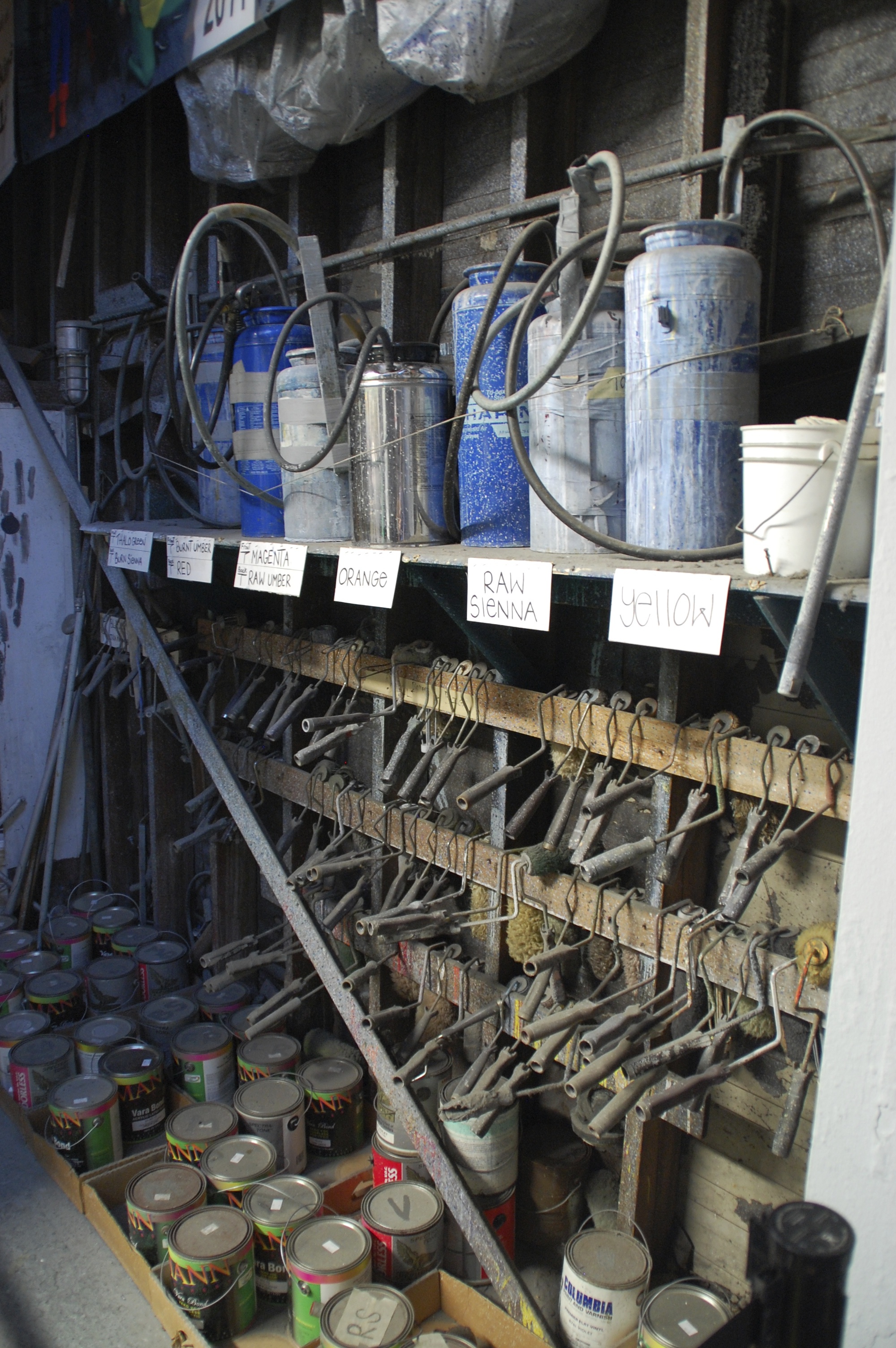
Paint rack with Hudson sprayers and roller mandles
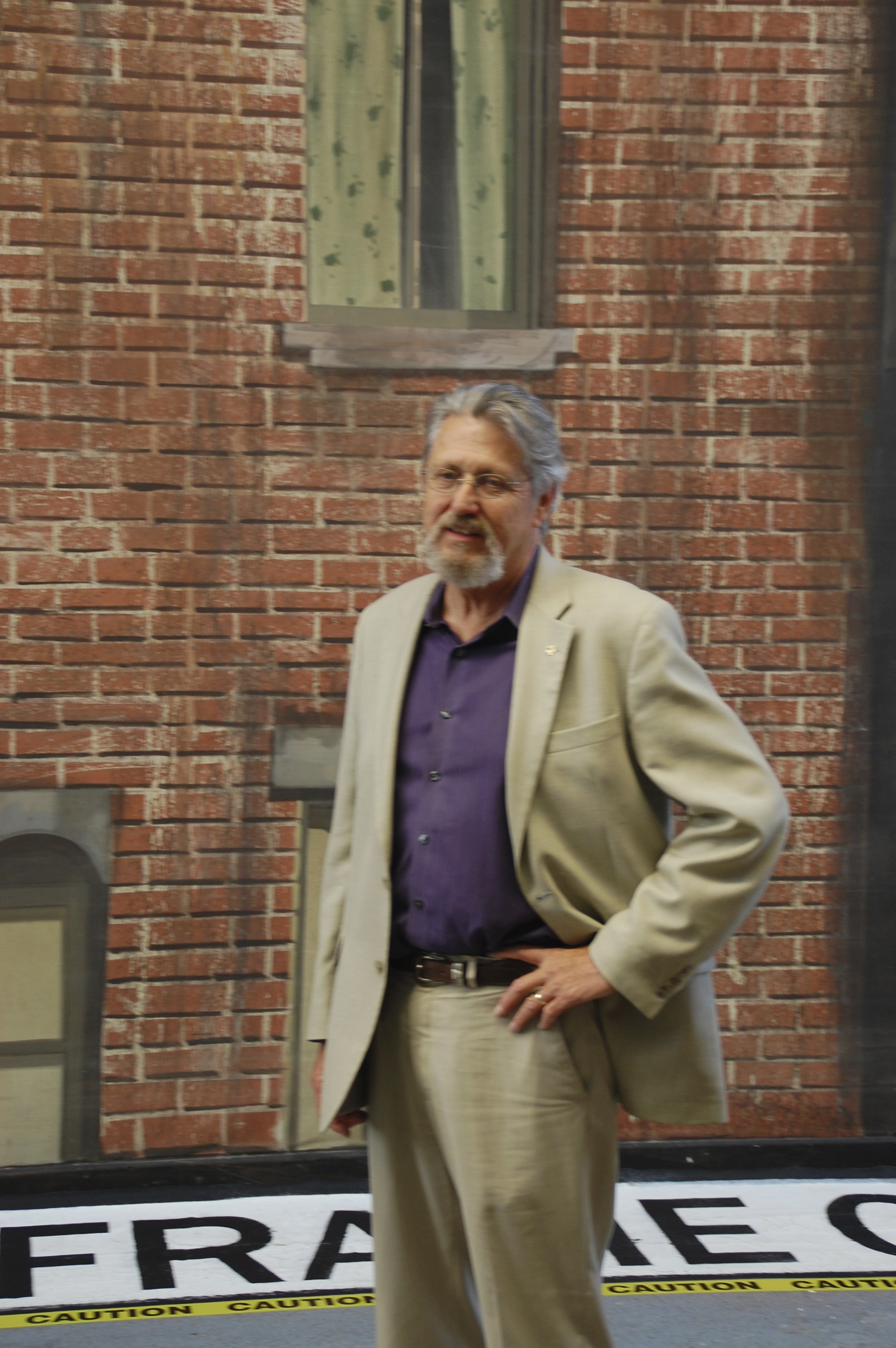
Art Directors Guild’s Associate Executive Director John Moffit in front of one of the many backings he painted while Head of the Scenic Department at Warner Bros. Studio
Large backing in progress on the large paint frame
Still from a Life Magazine article of the same space when it was the MGM scenic shop in the 1950’s.
1950’s photo of a backing layout in progress.
And finally, here’s a time-lapse video of a street scene backing being painted by scenic Donald MacDonald at J.C. Backings. Note how the canvas is back-painted so that it can be rear lit for a night shot.
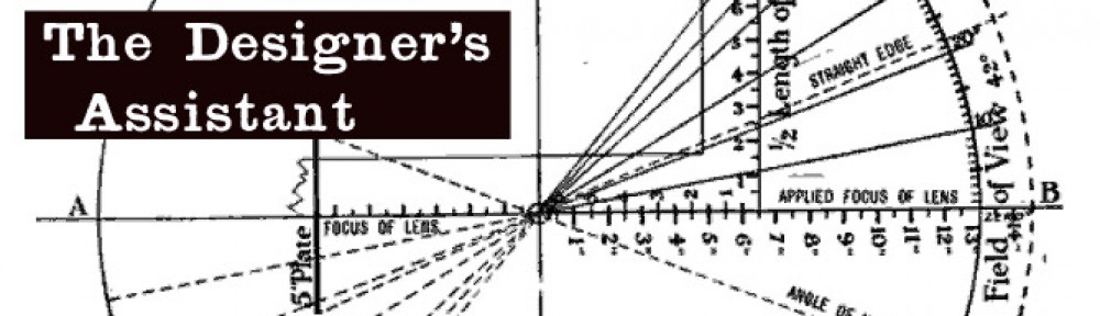
A lot of people take shots of sets and wonder how the focal length of their still camera lens compares to cinema lenses. Even if the capture format is 35mm film or a digital camera with a 35mm size sensor, the angles of view are not the same as with a 35mm still camera.
The reason is that the the film runs horizontally through a still camera instead of vertically as through a cinema camera, resulting in a larger frame in the still camera which in turn results in a wider angle of view with a similar focal length lens.
The lens angle chart below is similar to the traditional AOV acetates used in Art Departments for decades but this one has the equivalents for still lens focal lengths next to the cinema lens angles. (You can print out a pdf of this below, just have it printed on clear acetate.) Beside each cine focal length you’ll see the equivalent focal length with a full frame DSLR. If you are using a camera with a crop frame factor this will of course be closer to the cine focal length. In fact if you shoot with the Nikon D40 or similar, it will be almost identical in focal length numbers to the cine lenses.
On the chart I’ve drawn a full size outline of each sensor/frame size so that you can see the difference between the two mediums. You can use this chart on any size scale plan and it will give you a very close approximation to what you’ll see with a given lens. If you want to use it on elevations you’ll need to divide the angle by 1.33 to get the vertical angle.
For those of you who use iPhones for stills, you can download a AOV chart for the iPhone below, print it on acetate and compare in to the 35mm lenses.
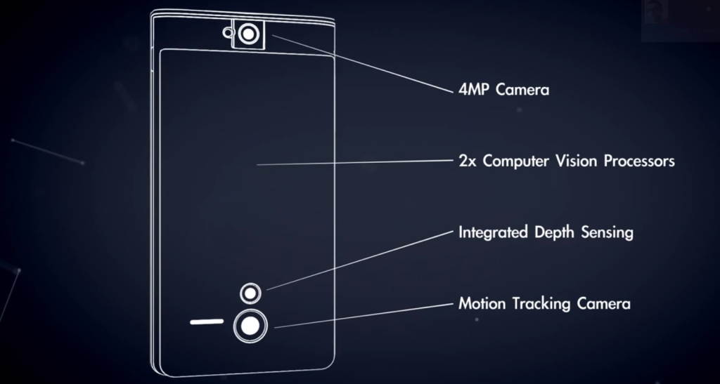
In February Google launched what they call “Project Tango”. They have developed a smartphone which is also a 3D scanner that can map the surrounding area and build a visual map of it. Processing over 3 million reference points a second, the device can build a virtual, scalable model of a room in the time it takes to walk through it.
Schematic of how the Tango device works
They have currently hand-picked 200 developers to create applications for the device which as of now only runs on Android devices. Imagine what this would do to those never-ending time-consuming location surveys. Would you ditch your iPhone if you could have an Android phone that did this?
Can’t wait that long? If you’ve got $4500 and want the latest in room scanners, go over to Matterport and watch their demonstration video of their room capture camera system.
A lot of times when you’re using your smart phone camera to take a shot of a set or location it would be nice to know what the equivalent view would be with a 35mm cinema / video lens.
I ran the numbers for most Apple devices and came up with the following equivalent focal lengths for both 35mm still cameras (full frame) and Super 35mm size sensors. Remember that although both formats are based on 35mm film stock, the frame for a still camera is a 1.5 aspect ratio with a frame width of about 1.417 inches. A Super 35mm frame is a 1.35 aspect ratio and the frame width is .980 inches.
Why only Apple? Well, the company readily makes their devices lens and sensor data available and it was easy to calculate. In the next post I’ll show you how to measure for your devices’ angle of view if the exact focal length isn’t published.
Please note in the following table the focal lengths for the given device have been rounded up to the nearest whole number so the equivalent lengths given are approximate.