‘Hand-Hewn’ vs. Machine Made: Comparing Historic Tool Finishes To Modern Methods – Part 1

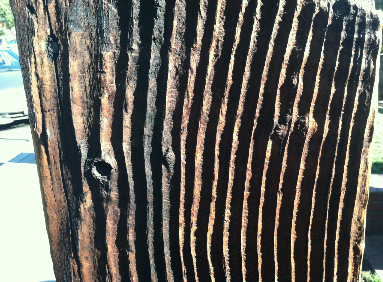
Creating period wood finishes for film and television scenery always involves a certain amount of subjective and creative interpretation. Usually the wood surfaces are finished to a level having more to do with the time period’s distance from modern times more than how old the set would look in relation to the time of the story. So usually anything set in ancient Roman times looks like it’s been through several hundred sandstorms, attacked with a grinder and sand blasted until the early growth rings are worn away from the late growth rings. There were certainly buildings that were very old at that time but there were plenty that looked much newer than the photo below.

weathered wood showing sunken early growth rings

weathered wood showing sunken early growth rings

I was working on a period film several years ago and I noticed that one of the other designers had called out the wood surfaces of their set to be finished as ‘hand-hewn’. I knew the surfaces would have actually been surfaced to a finer finish than a rough hewn beam and I asked why it needed to be so rough. They answered that being pre-machine age, other than furniture which would have required lots of sandpaper, they wouldn’t have had the ability to give the wood a smooth finish. I said that not only was that not true,  in many ways hand tools gave a superior finish to the tools of the machine age, and they had something better than sandpaper.  They laughed until they realized I wasn’t kidding.

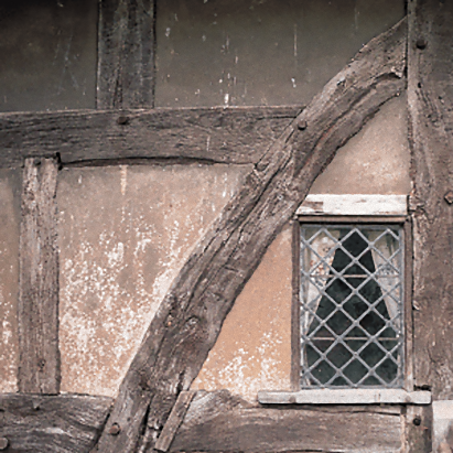
Let’s take timber framing. When most people think of a timber frame building they tend to think of the wood looking like this:

fachwerk3

16th century German timber frame or Fachwerk house.

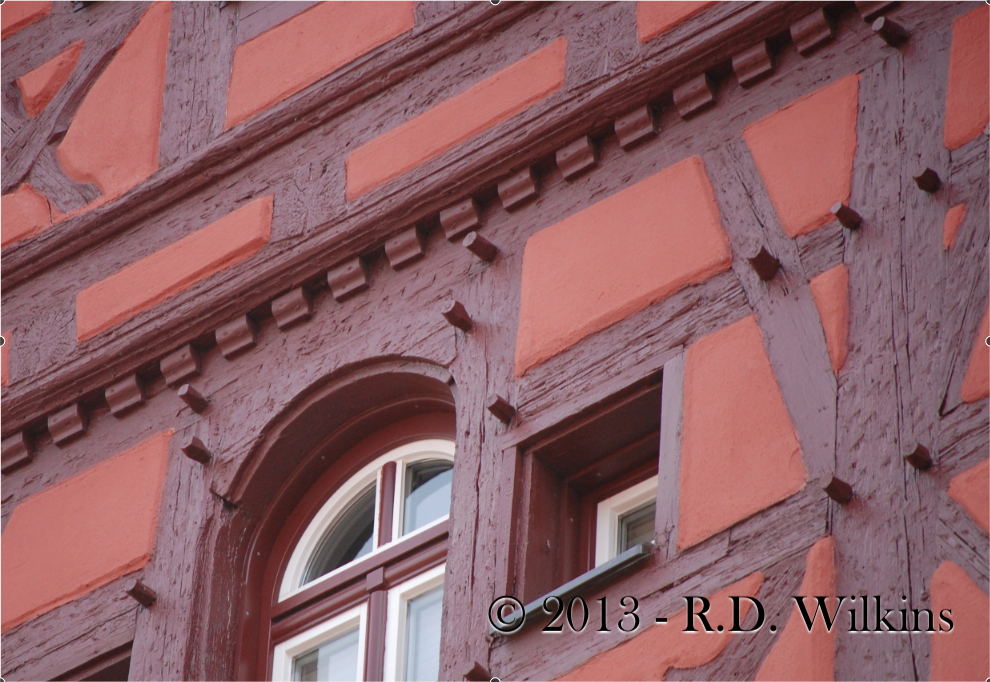
The wood didn’t look anything like this when it was built. The faces of the wood probably looked more like this (minus the checking or cracks):

restored German Fachwerk building from the mid 1600's.

restored German Fachwerk building from the mid 1600’s.


Partly because of this trend toward artistic license, and not understanding period construction which leads to misinterpreting the photographic research available (such as the photo below), wood buildings get designed and built with anachronistic finishes.


fachwerk2

The timbers of this fachwerk building were originally as smooth as those in the previous example. Many years later the faces were scored to act as a grip for the
plaster stucco-like finish that was applied at one time to ‘modernize’ it, much like some old interior brick walls were scored to accept plaster.


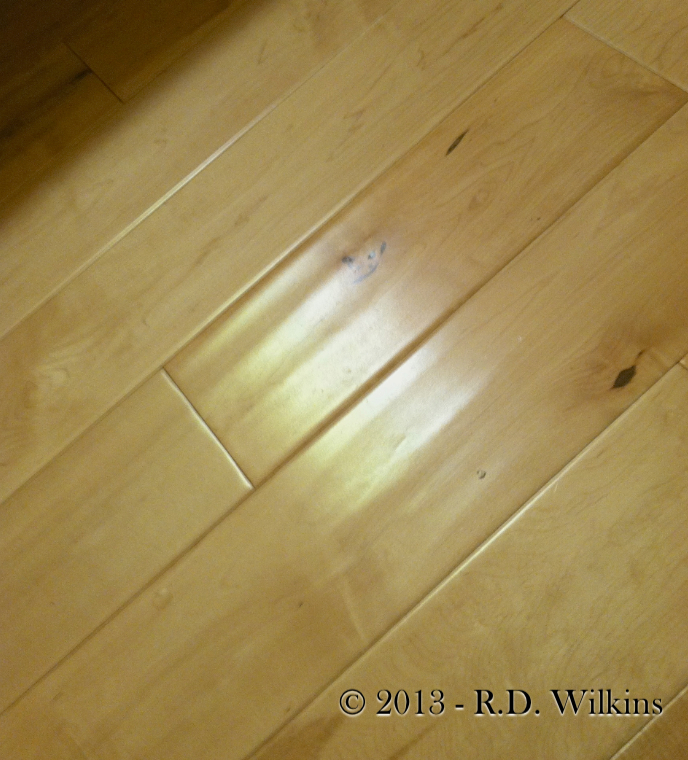
Even the building industry can take some of the blame. Here’s a photo of a popular flooring with a simulated jack plane finish. The plane had a curved blade that was used to quickly take a plank down before being planed smooth to its final thickness. A board with tool marks like this would not likely have been used in a decent dwelling.

fake jack plane tool marks


Today it’s hard to imagine doing all the work involved in processing wood from logs to a finished form without power machinery. How could a hand tool created a finish smoother than a modern tool, much less sandpaper? first of all, the way the tools work today is much different than the way period tools work. And, because it was  a much more labor-intensive process, they didn’t finish surfaces that wouldn’t be seen.

Let’s start with the big stuff. The process of taking logs from a tree to a piece of framing timber in the European tradition in the 16th and 17th centuries involved a number of types of hatchets.

Here’s a video by Christopher Schwarz on the use of hewing axes by Plimoth Plantation’s master joiner, Peter Follansbee:


By the 18th century the process involved not only the hewing axes and saws but an adze to square the sides followed by a broadax to smooth the sides, and possibly a drawknife to remove the axe and adze marks.

Here is a great little video by Ken Koons explaining the process:


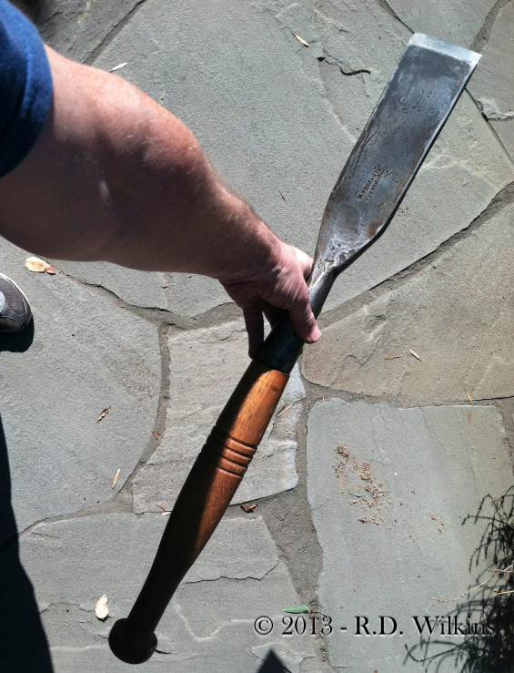
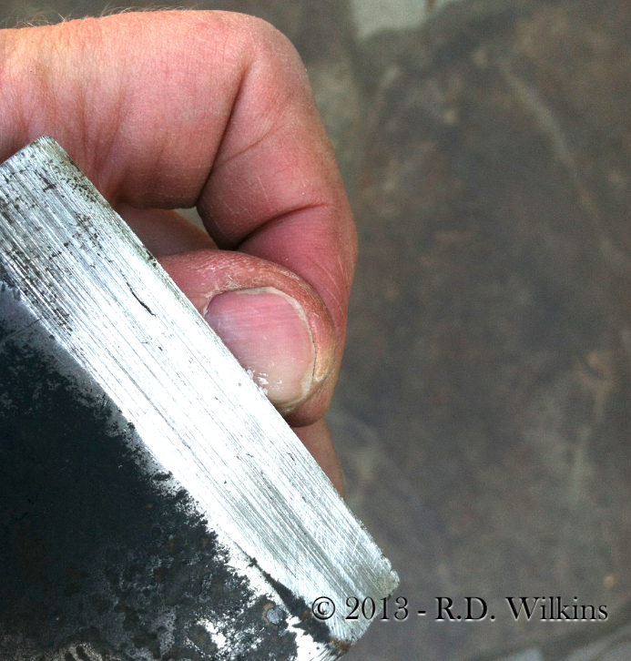
Once the mortises and tenons were cut they were cleaned up and smoothed using chisels and slicks, which were basically large chisels meant to be pushed by hand rather than hit with a mallet. The photo below is of the largest slick in my collection. Made in the late 1860’s in Ohio, it has a 3 inch wide blade. This big blade is certainly closer to a chisel than an axe as you can see from the closeup of the blade as it shaves off a sliver of my thumbnail. The blade will leave a very smooth surface.


A three inch wide framing slick from the mid 1800's

A three inch wide framing slick from the mid 1800’s

framing slick2


Here is a short video by John Neeman of a framing slick in use, you can see how quickly and cleanly it cuts a tenon.


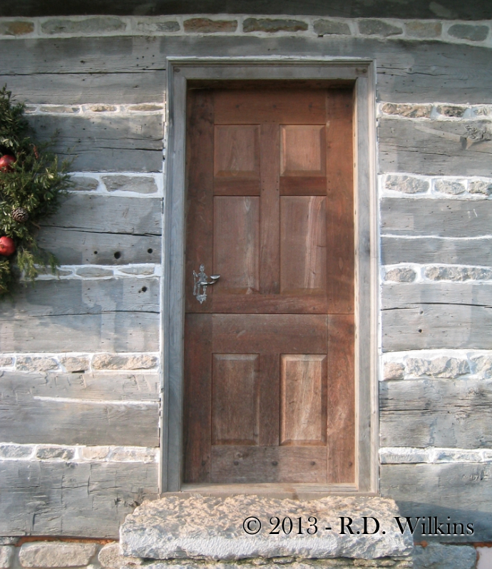
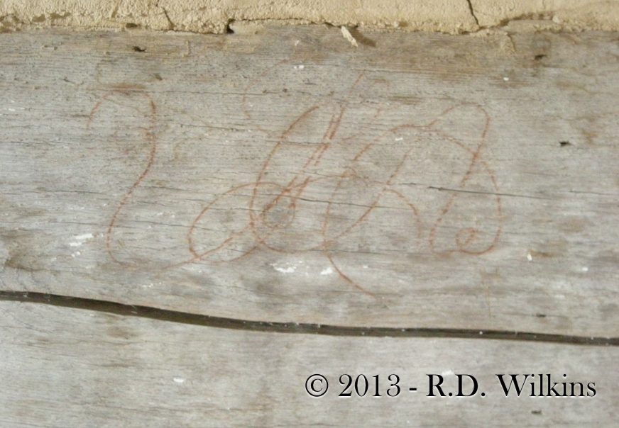
Cut timber surfaces were as smooth as their maker wanted, or needed them to be. Here are two photos of the Daniel Trabue cabin near Lexington, KY. The cabin was restored some years ago and returned to it’s 1797 appearance. The clapboard which had been applied later had protected most of the logs from decay. Notice the tool marks on the exterior logs. Now look at the second picture of an interior wall on the second floor. Here the German maker has signed his name with an 18th century cipher. Notice how clear the signature is. It was made with a traditional crayon made of beeswax and powdered vermillion used for marking out work while building. The crayon was found during the restoration, tucked above the front door lintel. The clarity is only possible because the wood surface is so smooth.

front door of the Daniel Trabue cabin

front door of the Daniel Trabue cabin

18th century cipher of the cabin's builder

18th century cipher of the cabin’s builder


Next week, in Part 2 of this post I’ll talk about and show you how traditional hand tools can actually create a finish that’s superior to their modern day counterparts and why our ancestors didn’t use, or need sandpaper to surface wood. Also, you’ll learn why every recreation of Noah’s Ark you’ve ever seen is dead wrong.

The HMS Bounty And The Blockbuster That Was Never Made

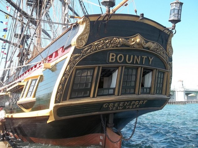
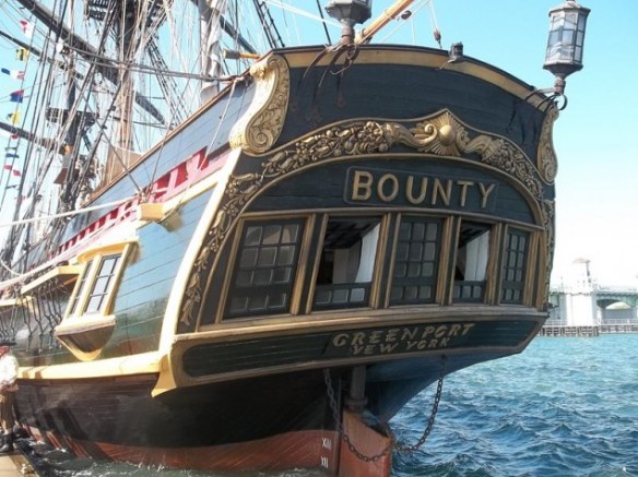
The Bounty in 2010. photo by Ebyabe

On October 29, as Hurricane Sandy bore down on the U.S. east coast, a distress call went out to the Coast Guard from the crew of the HMS Bounty. The ship was four days into a bid to avoid the ship being destroyed in harbor by the storm. The captain had decided that the best way to save the ship was to go to sea and sail around the hurricane. Now being swamped by 30 foot waves, the crew was forced to abandon ship. The captain and one of the crew were lost at sea before the remainder of the crew were rescued by Coastguard helicopters. Hours later I saw a photo of the ravaged ship as it went down, its’ mast tops shredded and its’ yards torn away.

The HMS Bounty goes down off the coast of North Carolina. Photo by Petty Officer 2nd Class Tim Kuklewski/ /U.S. Coast Guard via Getty Images

I looked at it and remembered climbing the shroud lines up to the main mast top and looking out to sea almost exactly 18 years before while surveying the ship for a film. It was to be a remake of the classic Errol Flynn pirate film, Captain Blood, and it would have been the most expensive film made to date. But the films fortunes were as bad as those of the Bounty turned out to be.

The HMS Bounty’s Rebirth

The ship was commissioned by MGM in 1960 for the 1962 film Mutiny On The Bounty starring Marlon Brando. Built in Nova Scotia, it was the first large vessel built using original ship’s plans. To make allowances for shooting and to hold a larger crew, the ship’s deck length was increased from nearly 91 feet to 120 feet with the beam, masting and rigging increased in proportion to the new hull length. Once the film was completed, the studio had planned on burning the ship but Brando protested and the Bounty ended up in Florida. It went through several owners before Ted Turner bought the ship and in 1993 donated it to an educational foundation where it was sent to a new home port in Falls River, Massachusetts.
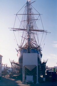
dock in 1994

Bounty in dry dock in 1994

When we went to survey her in 1994, she was on the rails in dry dock, a number of her futtocks were in need of replacement but we were assured the work would be completed in time for filming. Three of us crawled all over the ship the entire day, taking measurements, hundreds of photographs and video to document the existing structure for as-built drawings. Since the story of Captain Blood takes place in the 1680’s, over 100 years before the original Bounty, the ship was to be converted to an earlier vessel which meant applying a different stern, rigging and bow.

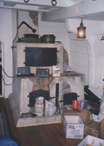
The ship still had most of it’s original fittings including the brick oven and the hand grained paneling below deck. Other than the repairs on the futtocks, she seemed still intact after over 30 years of sailing.
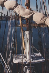
View from the main mast top. Photo- R.D. Wilkins
View from the main mast top. Photo- R.D. Wilkins

The Bounty's brick oven. photo - R.D. Wilkins

The Bounty’s brick oven. photo – R.D. Wilkins
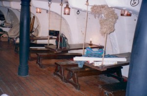
The crew mess area. photo - R.D. Wilkins

The crew mess area. photo – R.D. Wilkins
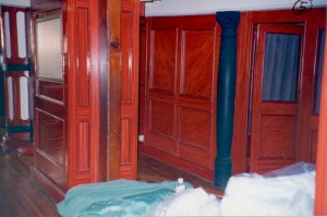
hand-grained partitions below deck. photo-R.D. Wilkins
hand-grained partitions below deck. photo-R.D. Wilkins

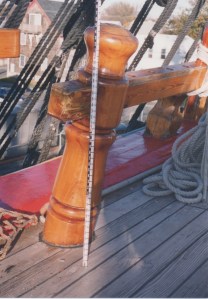
Survey photo of the fore bits. photo - R.D. Wilkins

Survey photo of the fore bits. photo – R.D. Wilkins

The great wheel and binnacle. photo - R.D. Wilkins

The great wheel and binnacle. photo – R.D. Wilkins
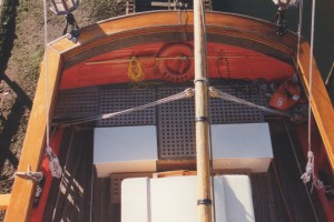
View of the stern from the main top. photo - R.D. Wilkins

View of the stern from the mizzen top. photo – R.D. Wilkins
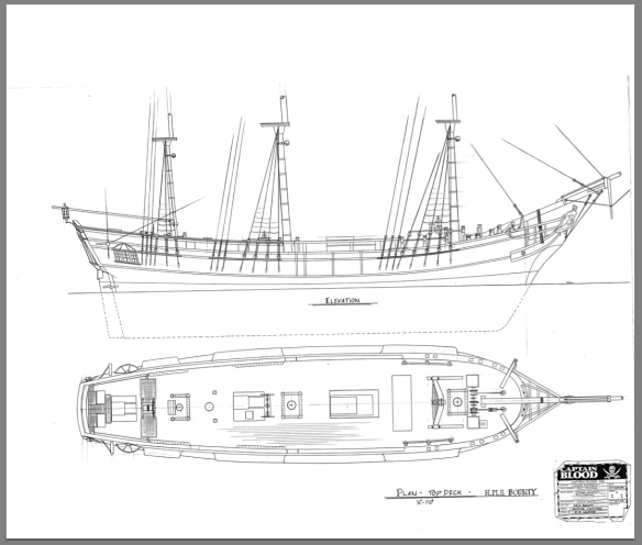
Drawing done from survey measurements in 1994. R.D. Wilkins
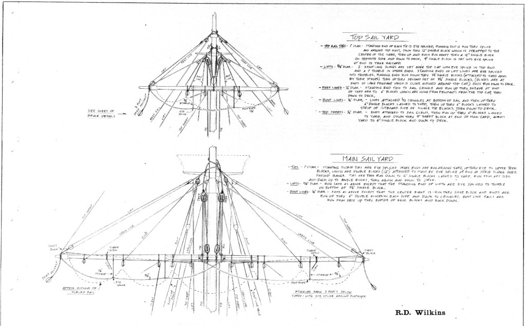
Drawing done from survey measurements in 1994. R.D. Wilkins

Period rigging details

Period rigging details for Bounty conversion.

Captain Blood Sails Again

Back in Los Angeles, design work proceeded under the leadership of Production Designer William Creber, who had been nominated for Oscars three times before. The Set Decorator was Eddie Fowlie, David Lean’s right-hand man who had done props and sometimes effects as well for the classic films, Lawrence of Arabia, and fulfilled five different roles on Doctor Zhivago as well as other films. When asked by the studio which credit he wanted for Zhivago, he first replied he didn’t care but decided on a special effects credit since it had involved the most work. He later wished he had picked another title since the effects were so good they were virtually ignored. It appeared to all that the film was made in snow in winter when it was actually shot in Spain, with thousands of tons of cheap marble dust used as snow. The beautiful winter ice palace interior was actually carefully applied paraffin. He had come out of retirement to do the picture, leaving his home in Spain. We were all a bit in awe of both of them, particularly Eddie given his pedigree with Lean. The director had just had his last film explode at the box-office and was the hot ticket in town. The scripts scribes were equally hot commodities and had recent successes of their own.

The plan was to do a remake of the popular Errol Flynn film from 1935, even though the common thought at the time was that pirate movies didn’t make money, (Jerry Bruckheimer would prove this wrong a few years later.) Popular yes, profitable no, This was mainly because of the cost involved in making them. Besides being a period film, it would involve creating a huge 17th century battle, creating at least four different period sailing ships and recreating a large section of the town of Port Royal. The initial projected budget suggested that it would be possibly the most expensive film made to date. That being the case, there were only a few stars that the studio was willing to gamble their money on, and the first choice was Arnold Schwarzenegger.
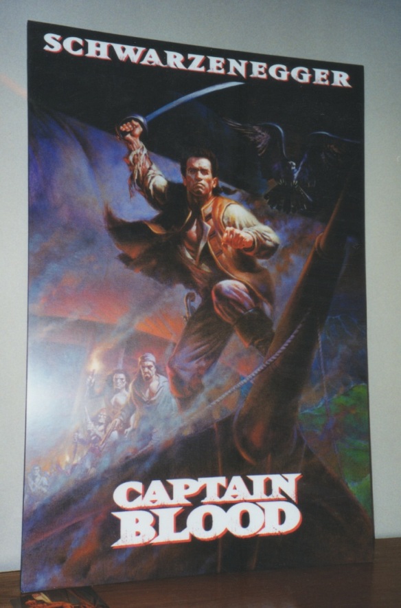
Proposed artwork for a promotional poster for the film.

Proposed artwork for a promotional poster for the film.

I was eager to quiz Eddie about his time with David Lean but he seemed a bit aloof and obviously did not suffer fools gladly. So, I thought I would offer something he would find useful. I brought in a rare out-of-print set of books from my library of which part was an inventory of ships of the period. One section listed every piece of equipment you could find aboard with illustrations and measured drawings, a Set Decorators dream. He looked up at me over the top of his glasses when I entered his office. “Eddie, I thought these might be a good reference for you”, I said as I laid the books open in front of him.

His jaw dropped slightly as he silently thumbed through them for several minutes. Without looking up he said, “Where did you get these wonderful books?” Then he said it reminded him of how he had done the props for Lawrence Of Arabia. He had an illustrator do a drawing of each piece he needed. The he posted them on his wall and would bring the various local artisans to his office, point to the drawings and indicate how many he needed.

I realized why you could never make a film like Lawrence today the same way and why the Art Departments of the period were so small. Today something like a camel’s saddle would be drawn in multiple versions by several illustrators, modeled in Rhino or Modo by as many as three different set designers, rendered, redesigned, remodeled, re-rendered, finally approved by the director, and only then would a set of working drawings be made. Eddie just found a person who understood what it was he wanted, gave him a sketch and told him how many he needed. But this was a time when directors hired people they trusted and let them do their job. They understood that THEIR job was defining the story and script and concentrated on camera placement and performance and didn’t involve selecting drawer hardware.

After that Eddie would chat about he times with Lean in the afternoons at tea time, which didn’t involve tea for Eddie, who preferred beer. He’d found a local shop in Santa Monica that carried imported beer, so each day when we’d walk to lunch, ( those were the days when we actually stopped for a proper lunch and didn’t eat hunched over our desks ) we would buy him two cans of his favorite beer.
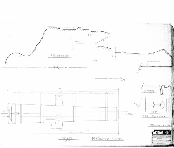
drawing for 18 pounder cannon tubes. At over 9 feet long, these were even shorter than the largest guns.

Drawing for 18 pounder cannon tubes. At over 9 feet long, these were even shorter than the largest guns to be made.
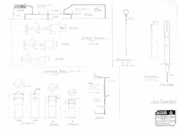
drawing of gun equipment

drawing of gun equipment

One day one of the producers was talking about the ship cannons and I showed him a mock-up of the cannon shot for the large 32 pounder cannon. He frowned as he took the 6 1/2 inch diameter ball and said it seemed puny. I walked him around the corner to where I had taped a full size silhouette of the gun that fired it, which was over 10 feet long and more than 4 feet high. He was shocked. It was then that I made the mistake of mentioning that the opening battle scene was based on a real battle, the Battle of Sedgemore in 1685. He looked surprised and said, “you’re kidding?” I said that not only was that based on history but the main character was also based on a real man named Henry Pitman. “That’s fantastic!” he said. I’m sure in his head he could see that sought-after card ‘based on a true story’ in the title sequence at the front of the film.

This revelation caused a lot of excitement and they asked me to do a little presentation for the director and producers about the real events behind the film. A few days later when I began the presentation, the enthusiasm quickly died. As I told them the real story it became readily apparent that serious liberties had been taken in Sabatini’s original book and worse, the events portrayed in the script didn’t match the real story either. The carefully crafted battle scene that took place at night in the swirling snow had actually happened in the middle of July where heatstroke would have been more a likelihood than frostbite.

It was then that I realized two important truths about the film industry;

1. – Working on a film about a subject you know a lot about is usually a very frustrating and ultimately disappointing experience.

2. – If someone, other than the Production Designer, says they want to know what it really was or looked like, it doesn’t necessarily mean they’ll change what they already have in their mind.

Most people just want research that is going to confirm or validate what they already have in the script or the image they have in their head. Maybe that’s human nature but it’s the same reason composers hate the temp music used during editing. After months of hearing a tune connected to a picture the director will end up wanting something “just like that tune”. It’s almost routine for a director to question a designer’s design choice by demanding to see research. And then when the image which validates the design is produced, the director will insist, “well, I still want my version instead.” Research that doesn’t validate their own ideas is worse than useless to them because it just points out their own ideas are many times based more on Hollywood clichés than reality.

Everything was proceeding nicely when we be can to hear rumblings that Schwarzenegger was thinking about pulling out of the movie. It was rumored that he had an extended ski trip planned that conflicted with the schedule. Someone else suggested that he was worried he would look ridiculous in 17th century knee breeches. For whatever the reason, a week later it was confirmed that he had pulled out of the picture. The momentum slowed to a crawl. With a picture this large, particularly a picture partly shot at sea, the weather plays a large role. If the schedule was pushed we would be into hurricane season in the tropics and that was something the studio didn’t want to contemplate. Another actor would have to be found and fast.

Because of the estimated budget, the studio sent a list of just five other actors that they considered to be enough of a box office draw to make the film feasible. I leave it to you to guess who those five were. As the week went by, each actor on the list passed until there was just one who had yet to decide.

In my naiveté, I had regularly been collating and forwarding research from my library that I though would be useful but never got a response about it. As each script revision happened it became apparent that it was being tailored to Arnold’s action hero persona with ever greater feats of daring and super-human agility. That last Friday, I got a call from the director’s assistant. She asked if I could send her additional copies of the all the research I’d been sending over to the director saying that the originals had been ‘lost’. The director was scheduled to leave on a plane for Paris that evening and wanted to take the research with him. It turns out the actor who was the film’s last hope was interested, but only if it was going to be a historically motivated picture. I wasn’t sure how they were going to explain why the script was so different from the research.

I don’t think I need to tell you what the actor’s decision was.
A “Sweet” and Cheap Architectural Detail Resource

Yes, I thought it was time for a bad pun. The “sweet” resource I’m talking about is the Sweet’s Indexed Catalogue of Building Construction. Not the modern version, mind you, but the earlier volumes. In particular I’m talking about the first one ever printed, in 1906.

Reprint copy of the first edition of Sweet’s

I found my copy in a used bookstore about 25 years ago, back when 3rd Street in Santa Monica was still a sleepy street lined with great used bookstores instead of chain outlets. It was a 1970’s reprint of the original, in great condition. But the most striking thing about it was how different it was from it’s modern relatives. This book was printed for people who actually drew details, and both wanted and needed to know how things were built.

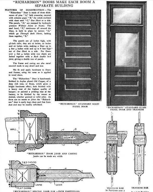
Most of the products pictured throughout the book had either detailed drawings or photographs of the items, with dimensions and cutaways showing how they operated and how they were integrated into the architecture of the building. This was a far cry from the ‘updated’ version, void of details, which was meant only to be a means of calling out the correct ‘part number’ on a drawing rather than giving the architect a full understanding of the specifics.

The original volume, if you can find a copy, has a green cover. The reprints will have a tan cover. The most useful ones for our work run from 1906 to the 1930’s. They aren’t easy to find but Google has solved that problem. Among the millions of books they have digitized for their ebook site are the 1906 and 1907 editions of Sweet’s. The digital editions aren’t as crisp as a printed copy, but the details you’ll glean from them are priceless. You can download it as a pdf and have it on your computer whenever you want to refer to it. Here is some of what you’ll find:

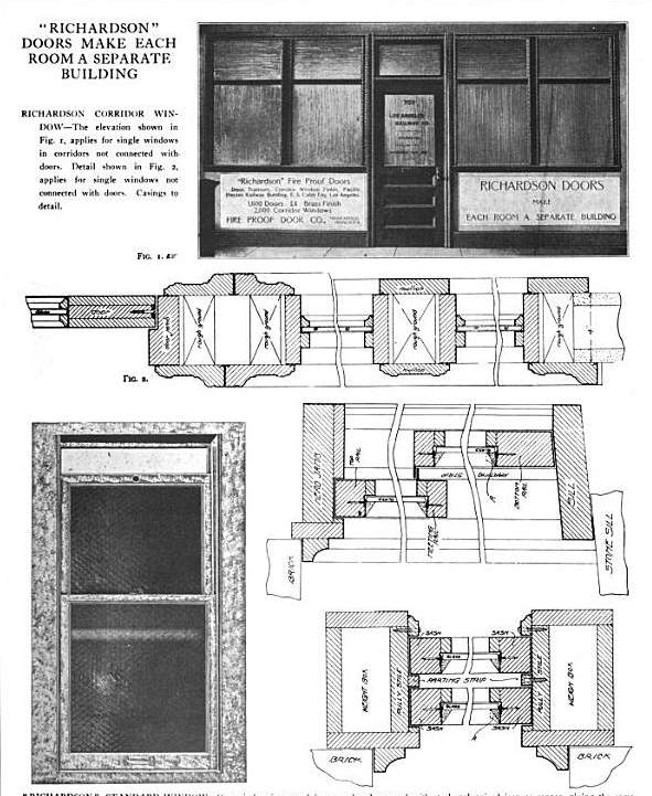
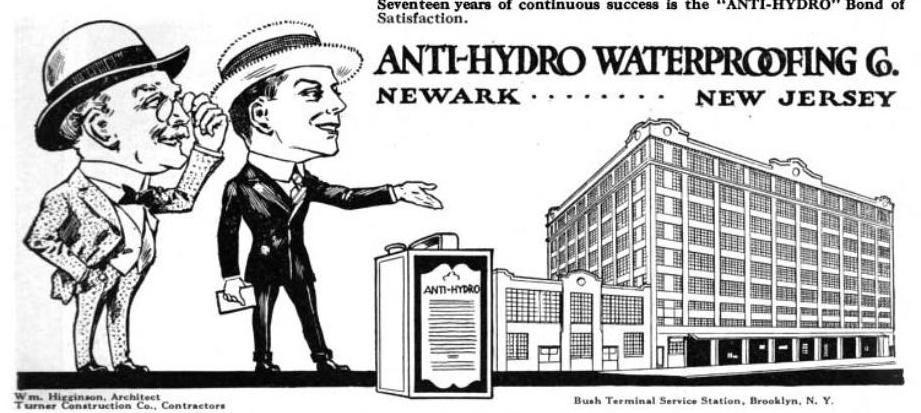
A sample of a typical advert featuring both photos and detailed sections

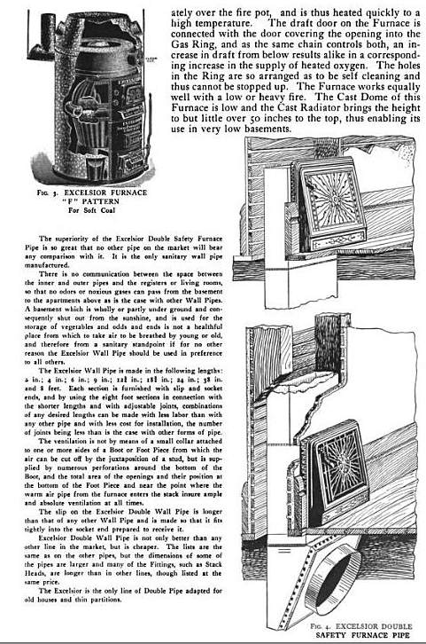
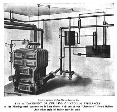
details of furnace and ducting showing how the duct and registers are attached to the wall framing

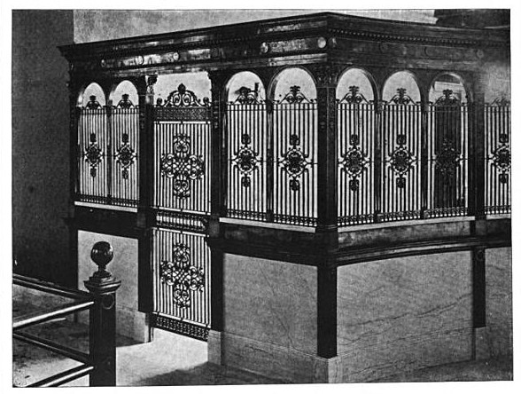
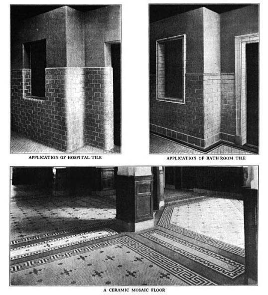
One of hundreds of photos showing details such as trim, ironwork and tile.

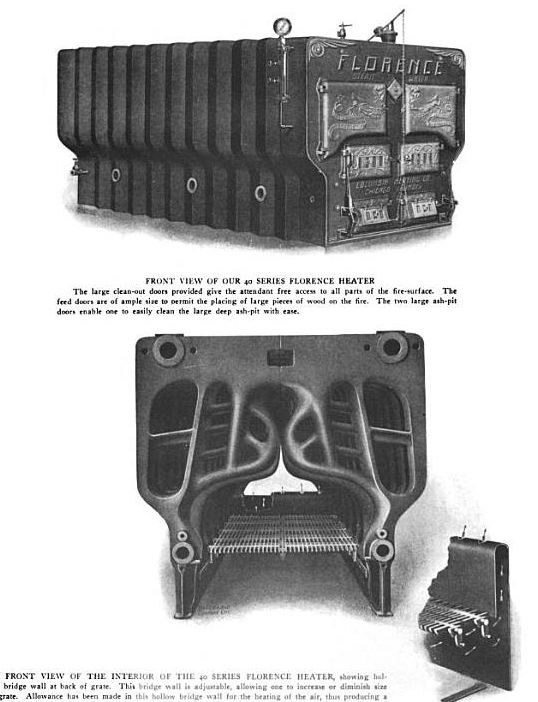
Detail of large furnace for an office or apartment building

An early central vacuum system

And here’s proof that people had MUCH bigger heads 100 years ago

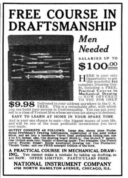
Another good source in Google Books is a magazine from about the same time period called The American Builder which has some good articles with details. This ad for a drafting course is great. Considering an average draftsman would have made about 35 to 40 cents an hour at that time, $100 a week would have been top dollar.

Graphic Standards From Across The Pond

Here in the US, the book we primarily turn to for all questions of an architectural nature is the AIA Architectural Graphic Standards. For our work, the third and fifth editions are the most informative because they were printed at a time when architects had to draw everything rather than order most elements pre-made. If you happen to be drawing up European architecture, though, it won’t do you much good.

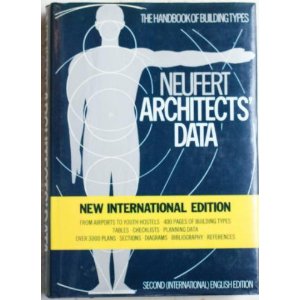
In the rest of the world, the architectural book most people turn to for similar answers is Neufert’s Architectural Data. Soon to be released in it’s 40th edition, the book is printed in 18 languages and is the architectural Bible in the metric world.

Ernst Neufert

Ernst Neufert worked at the Bauhaus as chief architect under Walter Gropius and later taught at the Bauhochschule until the Nazis closed it down in the early 1930’s. Seeing the need for a book that graphically laid out the architectural standards of the time, the book was first printed in 1936 and soon became a big success. Like Graphic Standards, the book is mainly a visual reference of architectural design and space standards for the European continent.

The book has had a number of English language editions, but the 1998 International is the most useful and easiest to use for the metrically-challenged. A large number of each edition are printed so it should be fairly easy to find used copies. You may have better luck throught British booksellers than second-hand businesses here.

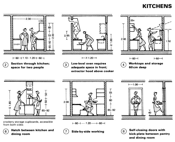
kitchen standards from an earlier edition

In Britain, The book many people refer to is McKay’s Building Construction. Originally published in three volumes over an eight year period, the recent re-publication has combined them into one book. The books are so popular in England that when they briefly went out of print, students were encourage to beg, borrow or steal to get a set.

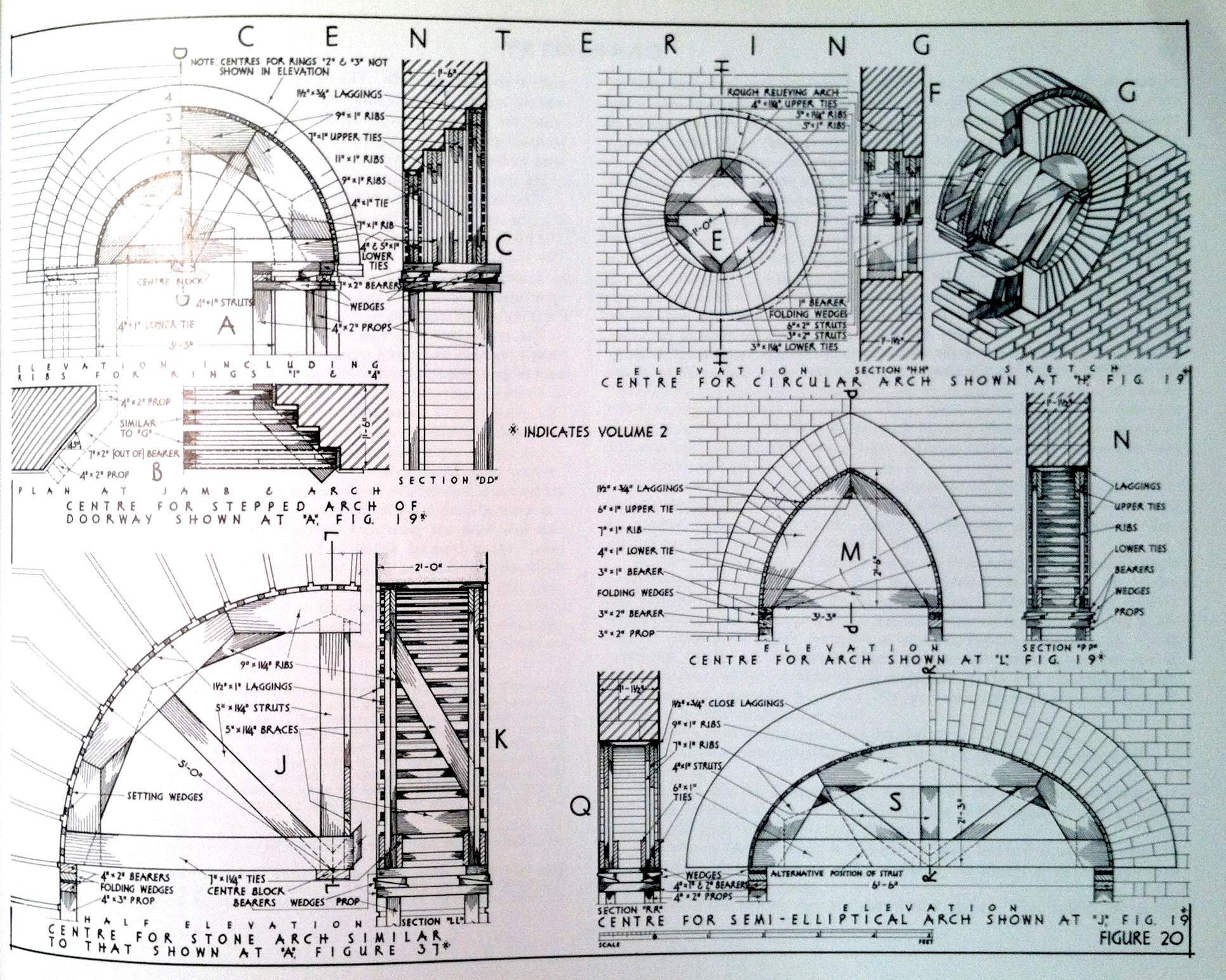
page on hand-cut stonework

Written by W.B. McKay, who was Head of the Building Department at both Leeds and Manchester colleges, the book is particularly useful for our business as it shows and describes exactly how the various methods of construction (wood and masonry ) are carried out. Filled with hundreds of beautiful perspective drawings by McKay, the book takes up where Graphic Standards ends.

Like Neufert’s, this can be had in used editions, the most recent from 2004. I found my copy in a bookstore in New Delhi, India, so you may have to search around. This is definitely a book that is worth the search.

If you’re in a hurry, you can order it here.

methods of forming masonry openings

Suggested Reading – “Illustrated Cabinetmaking”

Face it, having to design furniture or create construction drawings for it is not on most set designer’s list of favorite-things-to-draw. Sometimes you can get away with doing what’s basically a giant napkin drawing but most of the time you’ve got to get into some real details: like joinery, hardware and material specs. And there are the standards: what’s the widest bookshelf you can have before you’ve got a serious sagging problem?

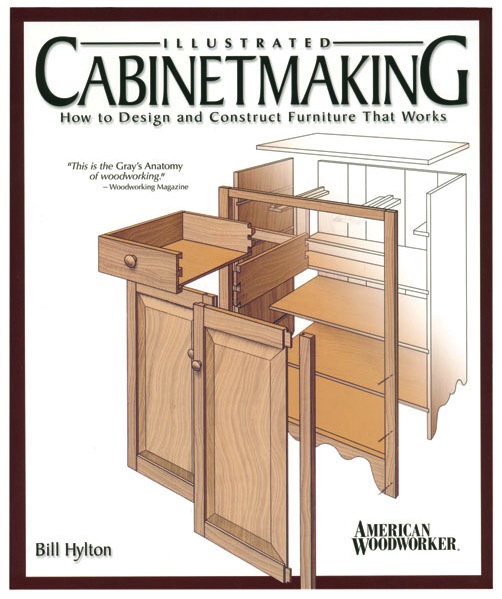
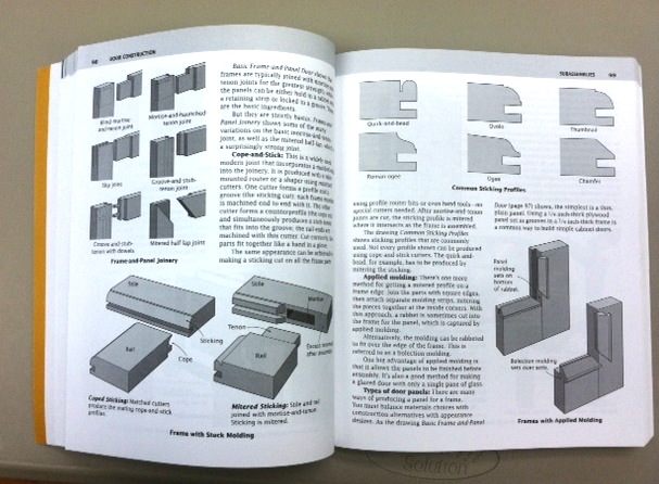
If you have only one book on furniture and cabinetry, Illustrated Cabinetmaking by Bill Hylton, is a good choice. Written for woodworkers, this book is an excellent reference for anyone who needs to draw or understand furniture design and construction. The book details over 90 different pieces and contains over 1300 beautiful pencil drawings. Each spread describes the piece in detail with exploded views and details, and gives design variations as well as sources for measured drawings.


There are also chapters on joinery, door and case construction, styles and the basic design standards for each type of furnishing.

Typical layout showing exploded views and details

Examples of joinery details

Each chapter is begun with a design standards chart

The book is published by Fox Chapel Publishing and retails for $24.95.

The Historic American Buildings Survey

The Historic American Buildings Survey, or HABS, was established in 1933 by Congress to  create work for unemployed architects and photographers during the Great Depression. Their mission was to document as many representative examples of American architectural structures as possible.

The teams of ‘delineators’ and photographers were hired from all over the country and would document every kind of structure, both public and private. The subjects ranging from well-known structures such as Jefferson’s home, Monticello, to simple barns and gas stations.  They didn’t know that much of what they recorded on vellum and in photos would be the only trace left of these structures as a great many of them were torn down over the preceding years.

In 1969, the Historical American Engineering Record was started as a ‘sister’ agency to record historic engineering and mechanical structures. The HABS / HAER collection, housed and maintained by the Library of Congress, now numbers over 500,000 drawings of 38,000 structures that range from Pre-Columbian ruins to the 20th century. Much of the collection is digitized and is available through the Library of Congress website.

Besides containing a wealth of architectural details, the collection is also a virtual museum of architectural drawing styles. As you look through the collection you can see how the drawing styles of the ‘delineators’ changes as the years pass. The very artistic ‘hand’ of the 1930’s and 40’s gives way to the more spare and graphic styles of the 60’s and 70’s. The collection continues to be added to each year and working on HABS surveys is a right-of-passage for many architectural students.


Below is a beautiful example of a drawing of hardware from 1940. The influence of that period’s drawing style in set design drawings will be obvious to those who have been in the industry since the pre-CAD days.

hardware from the La Rionda Cottage, New Orleans, 1940


Below, a drawing of details from an early Texas home, drawn in 1934.

Texas residence moulding details, 1933

Many of the structures documented were only photographed, but quite a few were documented with drawings as well. A typical survey may include as few as 3 or 4 sheets of drawings. Some contain as many as 20 to 30 sheets of drawings which include moulding and hardware details.

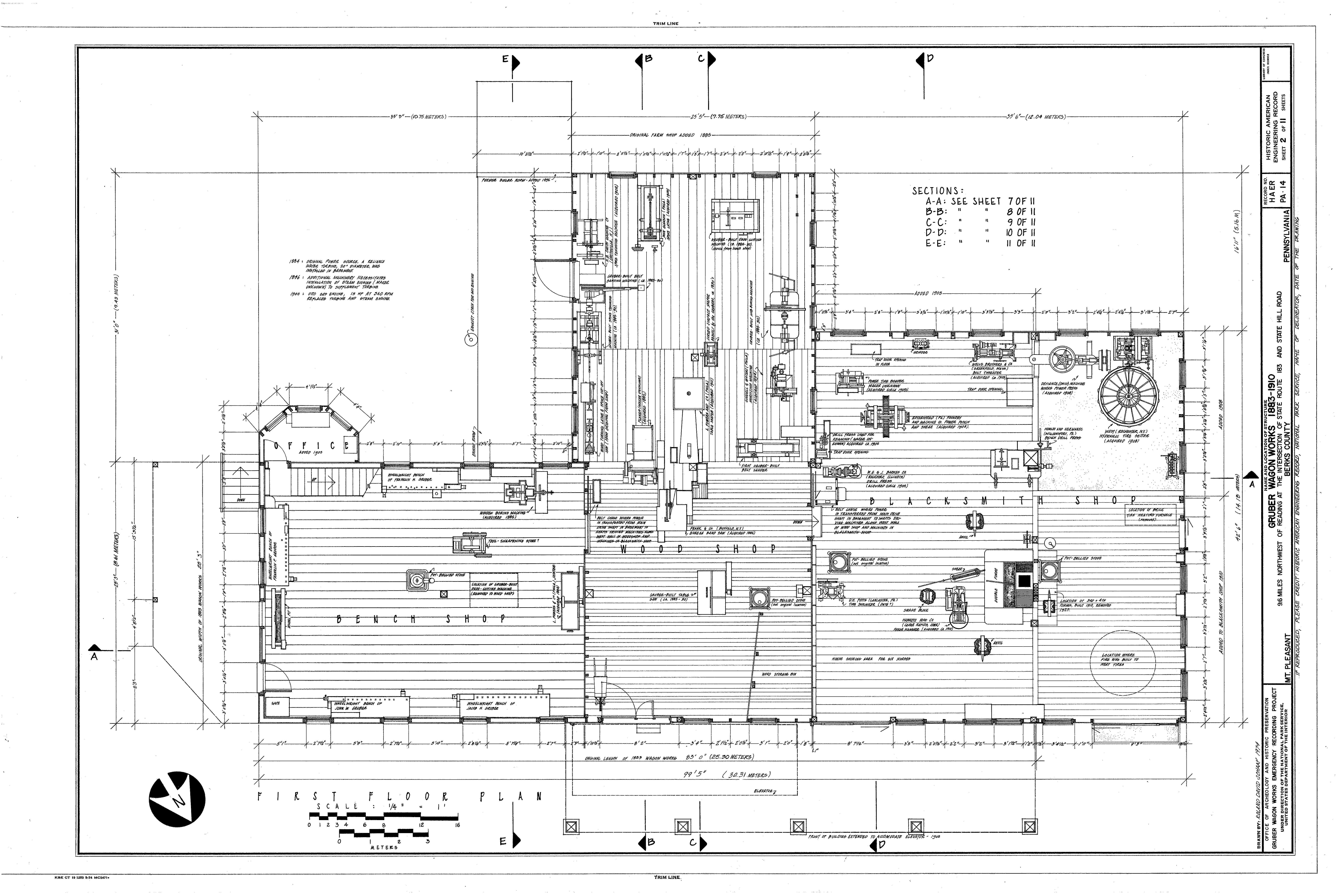
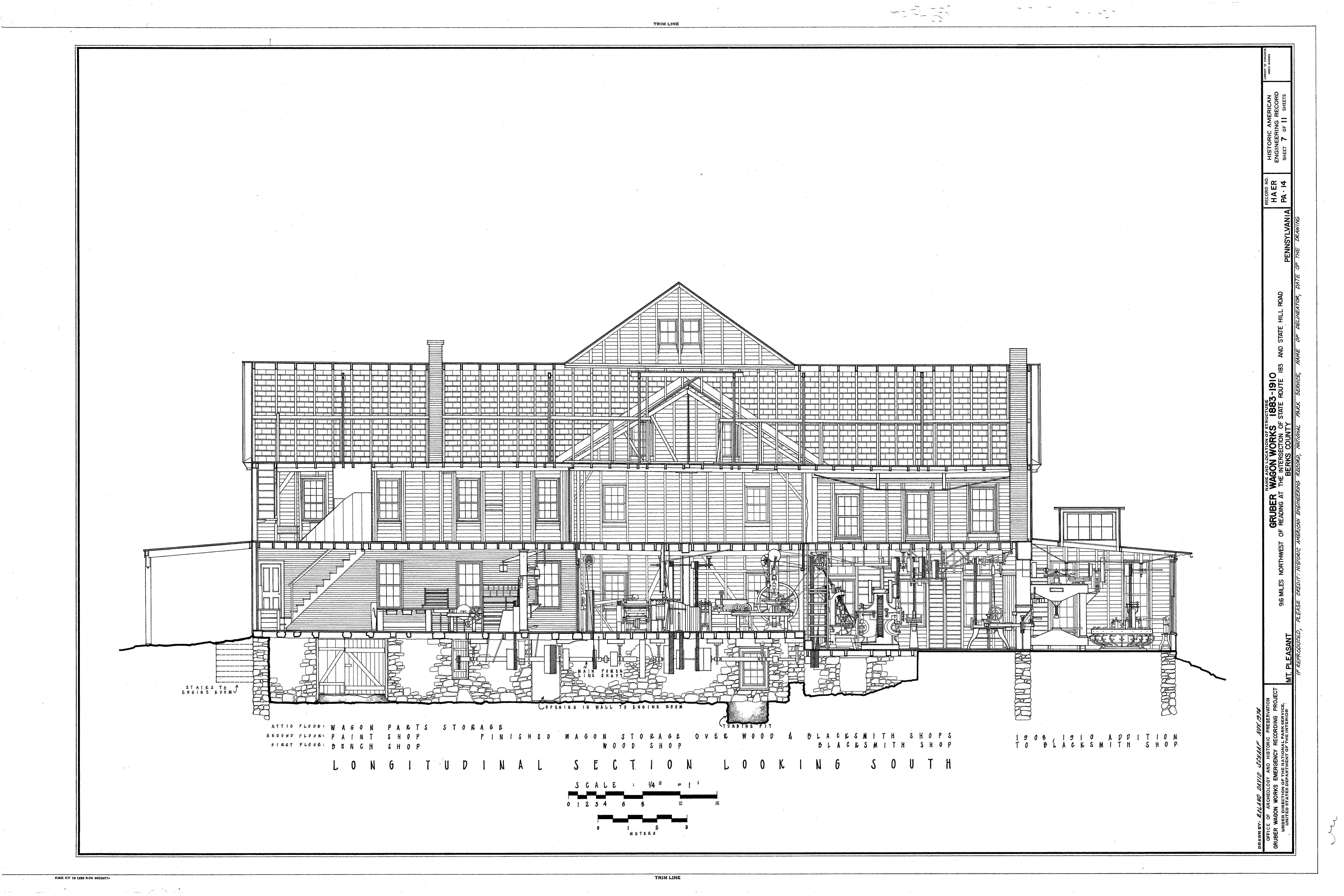
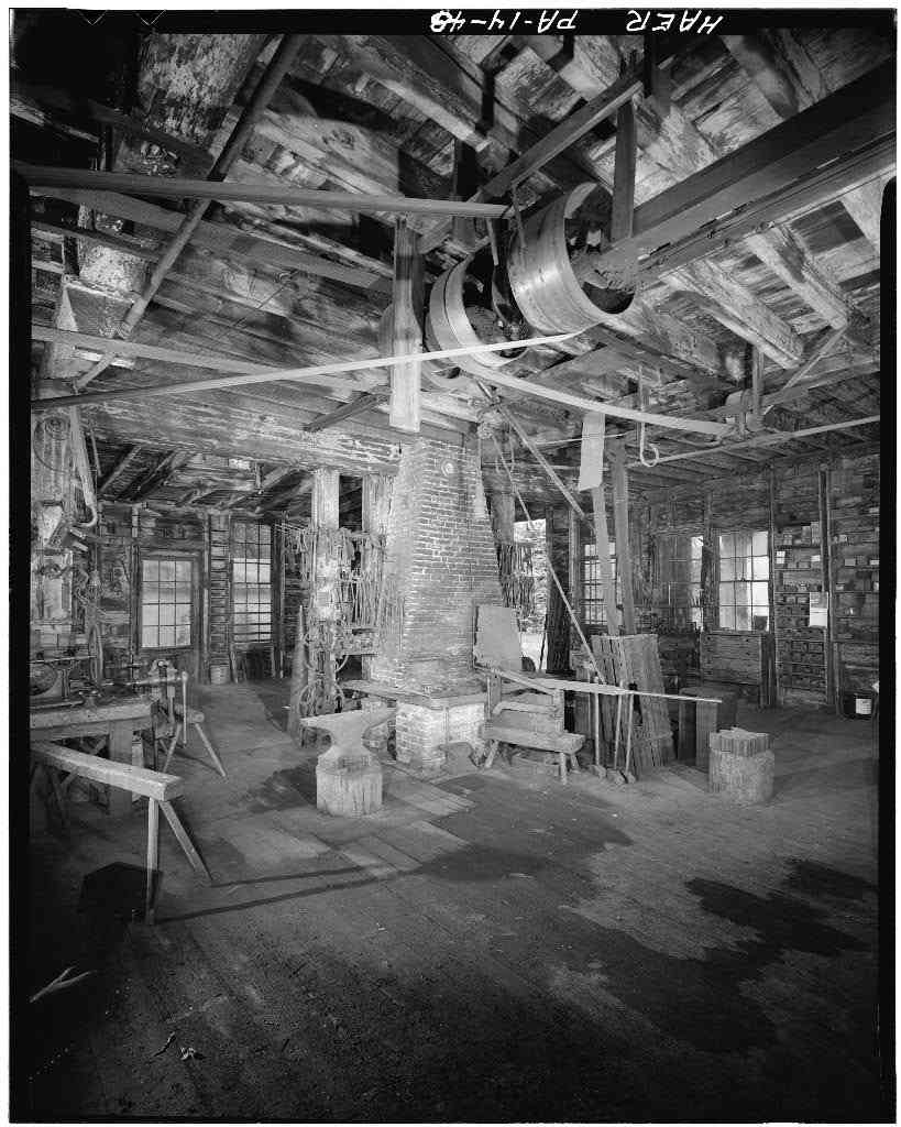
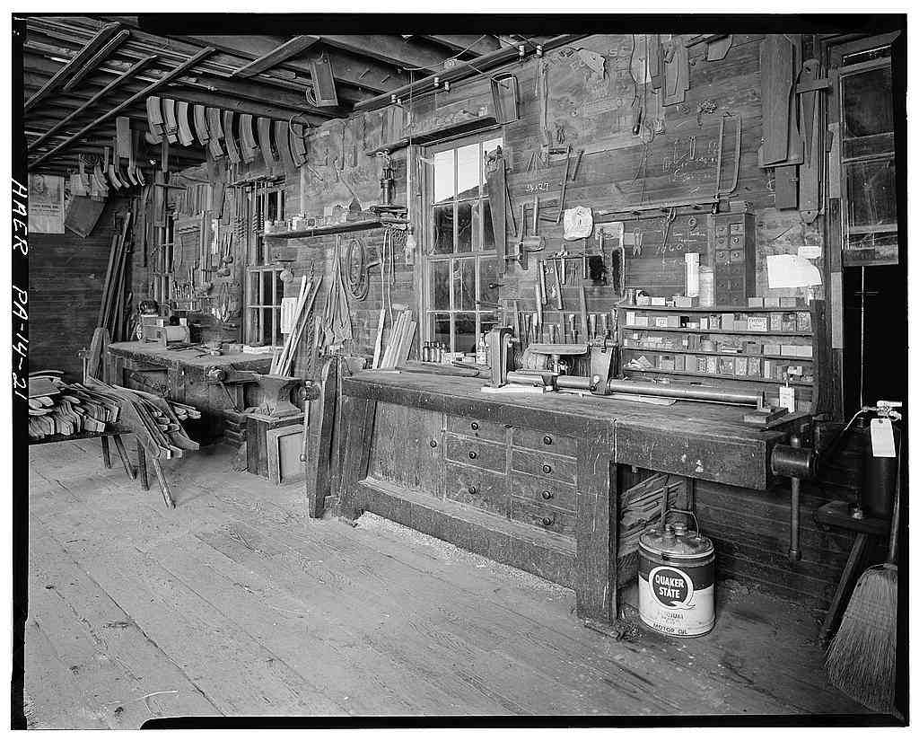
Some, like the 1883 Gruber Wagon Works in Pennsylvania were done as an ’emergency project’, executed when a structure was either in danger of being demolished, or in this case, on the verge of being dismantled and moved to another location. The Blue Marsh Lake Project in the area was the reason for this structure’s relocation.

Documented in 1974 by the HAER  in 11 sheets of drawings and 215 photographs, the wagon factory was a rare existing example of late 19th century American industrial age. It contained most of the original belt-driven machinery, still in their original locations.

1974 HAER survey plan of the Gruber Wagon Works


Longitudinal Section

photograph of forge area

photograph of workbench

As a reference and research site for our line of work, it’s pretty hard to equal it. Drawings can be downloaded as a reference tool in either a smaller file size for letter-size copies, or at full resolution for larger prints.

You can search by site name, region, building type or one of a dozen other search terms. But, plan to set aside a fair amount of time when you do a search, as you will quickly find yourself distracted by the huge variety of the material in the collection.

You can find the site at:

http://memory.loc.gov/ammem/collections/habs_haer/index.html