Art Directing Bomb Targets

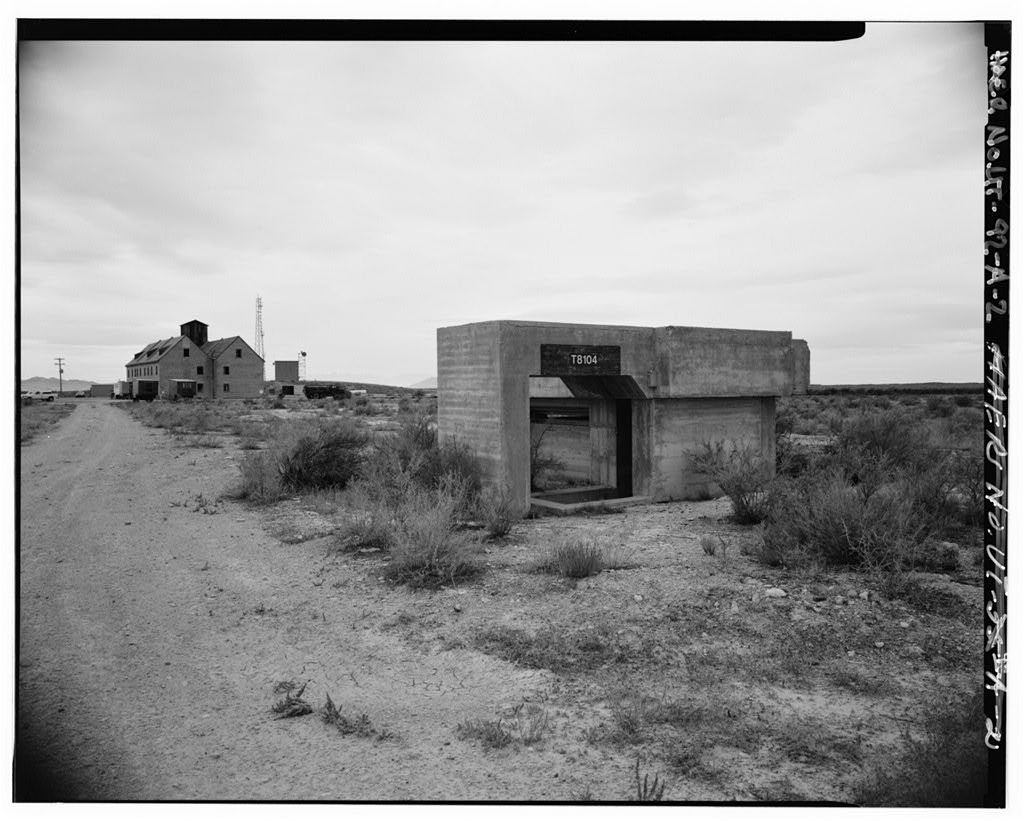
Remnants of “German Village” and observation bunker – HAER archives , HAER UTAH, 23 DUG, 2A-2

In the middle of the Utah desert there stands a brick three-story copy of an early 20th century German tenement building, a relic of World War II and a secret program that involved the RKO Studios Art Department.

Stories about Hollywood’s creative elite being involved with the military during World War II are part of its history and mystique. But it wasn’t until recently that I had found much information about any exploits involving Art Directors or Art Department personnel in the war effort beyond work on films contracted by the government.
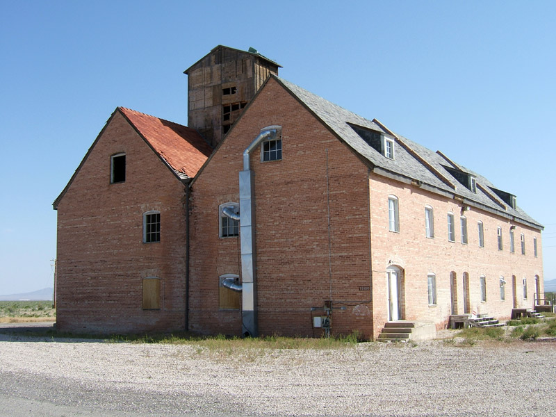
Remaining structure from 1943 – U.S. Army photo

While I was doing some research for a documentary, I was looking through past articles in the German magazine Der Spiegel and my eye caught a story entitled,  Angriff Auf “German Village”. Curious as to why part of the title was in English, I scanned the article and saw the words “RKO Studios.” The story recounted a secret U.S. government program designed to test the effectiveness of firebombs by building a mock German and Japanese village in the middle of the Utah desert. The top-secret program would involve the help of a number of renowned architects and the RKO Studios Authenticity Division. What was the “Authenticity Division”? My interest was piqued.

Once the United States entered the war it became apparent that in the event that gas and biological weapons were used, there had to be a place far enough away from populated areas to test these and other weapons. Roosevelt set aside over 120,000 acres in the Utah desert as land for weapons testing near the Dugway Mountains. By mid 1942 The Dugway Proving Grounds was open for business.

The U. S. Army had made it a point early in the war to not target civilians during bombing raids but was now facing pressure from the British to do so. After being bombed continuously themselves, as far as the British were concerned, the ‘gloves were off’.

Churchill pushed Roosevelt to deliver 500,000 top-secret ‘N’ bombs, which contained anthrax. He surmised that with the munitions he could wipe out at least half the population of the 6 largest German cities in one week. Roosevelt blanched at the idea and his Secretary of War argued that the U.S. didn’t want to help perpetrate an atrocity on the level of Hitler’s own terrible acts. Roosevelt instead offered to provide a more effective firebomb to help in Churchill’s aim of destroying Berlin. Previous attempts with the weapon had been ineffective because of the predominately masonary construction of the tenement buildings in the city center.
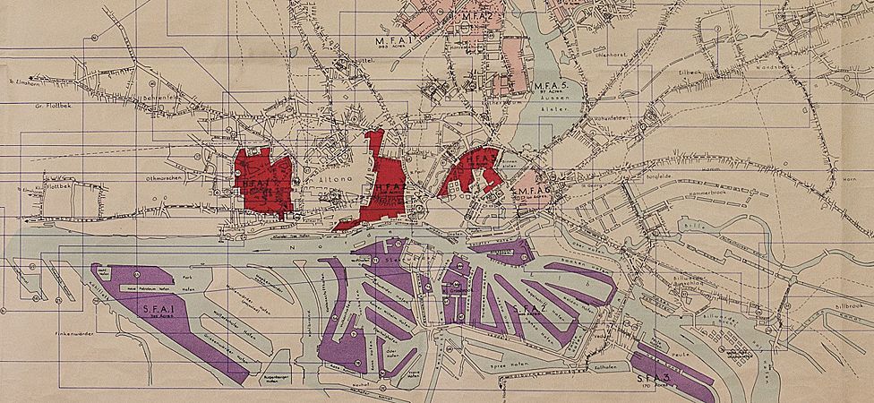
Fire Hazard map of Hamburg produced by the British in 1944. The red areas show the areas most susceptible to fire

Fire Hazard map of Hamburg produced by the British in 1944. The red areas show the areas most susceptible to fire


Like nearly every major corporation, Standard Oil was contracted to work for the military during the war and began developing an improved incendiary bomb. In comparison to high explosive bombs, incendiaries were designed to start fires. Standard Oil had designed the M-69 bomb, which contained a jellied gasoline, making it harder to put out a fire it started.  When white phosphorous was added, it made a deadly combination of which even a pea-sized glob could burn a human limb down to the bone in moments.  The substance burned furiously even when submerged in water.

Roosevelt ordered it to be tested immediately and suggested that exact copies of German and Japanese houses be built to test them on.
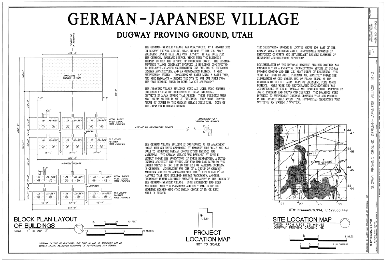
HAER drawing of original village plan in 1943 – HAER UR-92 sheet 1

At some time in early 1943,  RKO Studios was approached by the Standard Oil Development Company to authenticate and design furnishings for the German Village portion of the test area. Many people have attributed RKO being sought out because the studio had produced Citizen Kane, but it would be years before Kane was considered the masterpiece it is today.

What is more likely is that  RKO was approached because someone at Standard Oil had been to the movies recently.
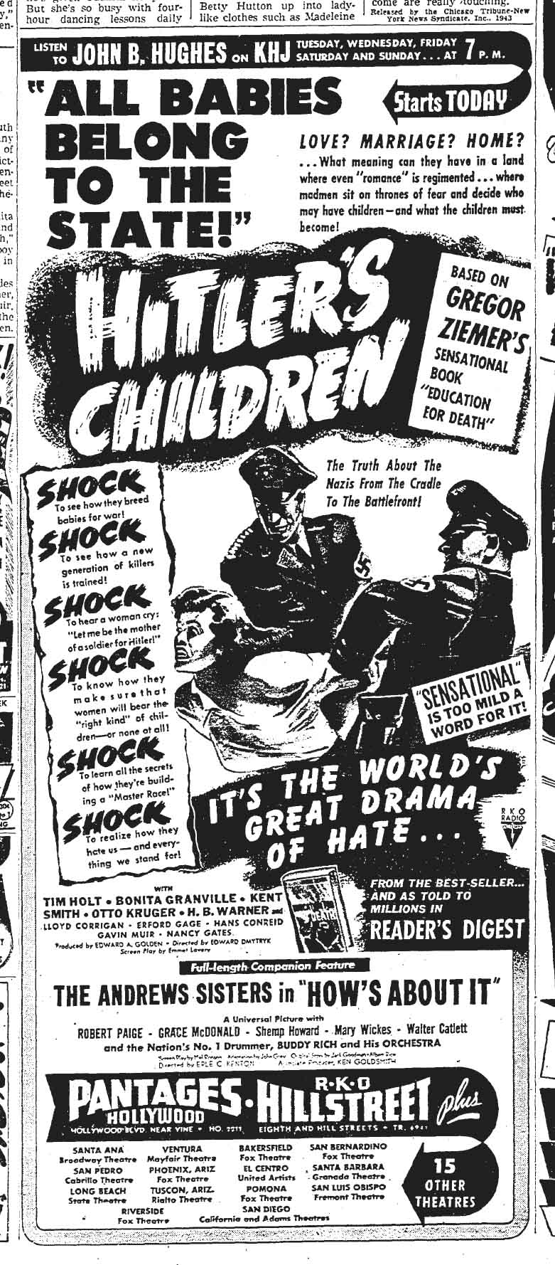
L.A. Times newspaper ad from the film – Feb. 24, 1943 – L.A. Times archive

On January 6 of that year, the studio had released a picture entitled, “Hitler’s Children” which was immediately a blockbuster and would become the biggest success of the studio to date. The film, based on a book, recounted the story of a young German-American girl trapped in Germany and forced to participate in the Lebenborn program, where young girls were encouraged to become pregnant out of wedlock to provide future soldiers for the Reich.  Because the film had a patriotic purpose, that of showing the horrors of life in Nazi Germany, the ethics board approved the film even though it contained such racy material as the lovely starlet Bonita Granville’s blouse being torn from her back and then whipped. It made for great box-office receipts. Made for around $200,000, the studio knew they had a winner the opening weekend. The Pantages Theater in Hollywood reported that “records for initial attendance were smashed to smithereens.” The film would end up making back nearly 13 times the original investment.

film still of young stars Tim Holt and Bonita Granville – RKO Pictures

The film’s director, Edward Dmytryk was one of my Directing instructors at the American Film Institute. While discussing the huge bonuses being handed out by the studios,  he recounted that “Hitler’s Children” was so successful the studio gave him a $5000 bonus. While paling in comparison to today’s bonuses, the sum was quite a substantial one at that time.

Because the movie dealt with domestic life in Germany and involved creating typical German interiors, the studio would have been an obvious choice for the job of recreating accurate dressing of civilian apartments. The Art Directors on the film were Albert D’Agostino, who was the Supervising Art Director for all RKO films, and Carroll Clark. It’s not known if they were the individuals actually involved in the government program.
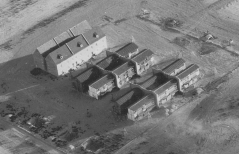
photo of completed village in 1943 – U.S. Army

A local Utah contractor had been hired to build both villages, which were side-by-side. With a mandate of less than two months to complete the buildings, the contractor pleaded for help with getting manpower and was allowed to use inmates from the Utah prison as construction workers.
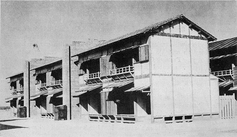
photo of completed Japanese homes 1943 – U.S. Army

The Japanese Village was designed by the Czech architect Antonin Raymond who had worked with Frank Lloyd Wright on the Imperial Hotel in Tokyo. He had set up his architectural practice there and would become known as the father of modernist Japanese architecture. Intimately familiar with the typical wooden structure of Japanese houses, he provided construction drawings and suggestions for building materials.

The German Village had been designed with assistance from the famous architects Erich Mendelsohn, Konrad Wachsmann and others from the Walter Gropius group at Harvard.  The structure was designed as a duplex unit divided into 6 apartments, all having a second floor and an attic, which was the most flammable part of the building.
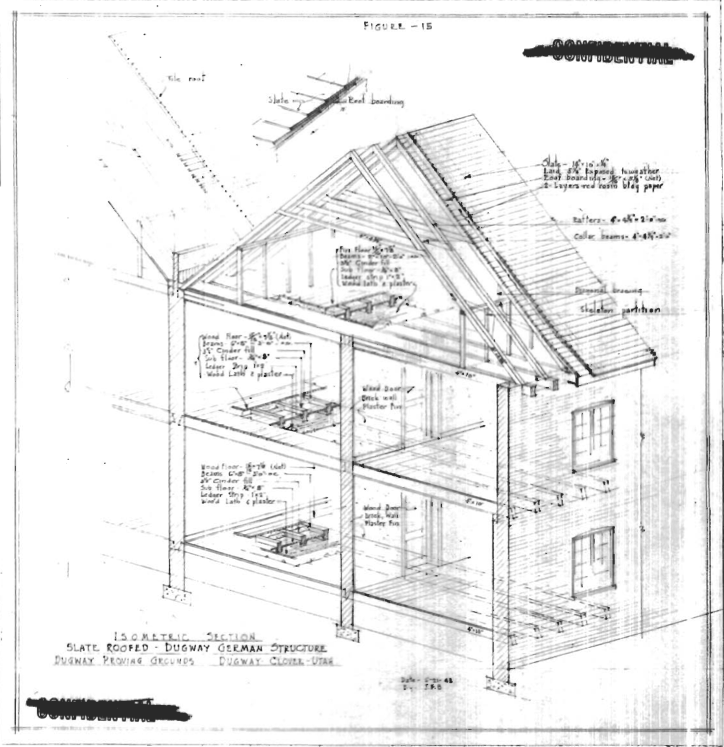
construction details of German tenements – U.S. Army

The structure was mostly masonry and the floors of this type of building were not only more massive, they contained a 3 1/2 inch cinder infill that made it very difficult for a fire to burn more than the upper floor and attic. Because of this the first floor was left unfurnished and only the top floor was dressed.

The list of furnishings needed to dress the buildings for the tests was staggering considering they had to all be built in a very short time. Over 760 pieces of furniture were called for as well as over 700 mattresses, pillows and drapes and over 900 tatami mats were needed for the Japanese buildings.

Every tatami mat in San Francisco and Hawaii was rounded up and sent to Utah. When these proved insufficient, others were constructed using Mexican ixtle fiber as a substitute. A shipment of lumber from Murmansk was captured and used to simulate Japanese building materials and rattan was used in place of bamboo.
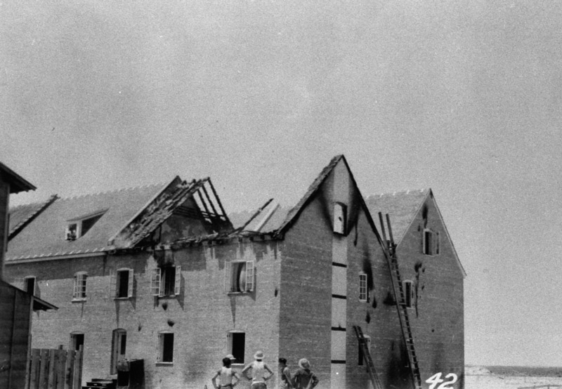
German tenements after first bomb test – U.S. Army

The German Village was a block of 6 rowhouses built back-to-back to mimic the German ‘mietskaserne’ or ‘rent barracks’ which were the typical low rent living quarters in the large cities such as Berlin. Normally 5 to 6 stories high, the ones built at Dugway were only two stories plus the attic area. The attics were the only portion of the brick buildings that were mainly wood and were the target of the incendiaries.

One side was built with the western German style of slate over boards while the other side’s roof was covered with tiles over battens as was common in Berlin. Douglas Fir and Southern Pine were used to simulate the typical German Kiefer wood for the flooring, roof joists and beams. Because the tests needed to be as accurate as possible, soldiers were assigned to constantly spray the exposed inner framework with water to keep the wood’s moisture content from falling in the desert’s low humidity.
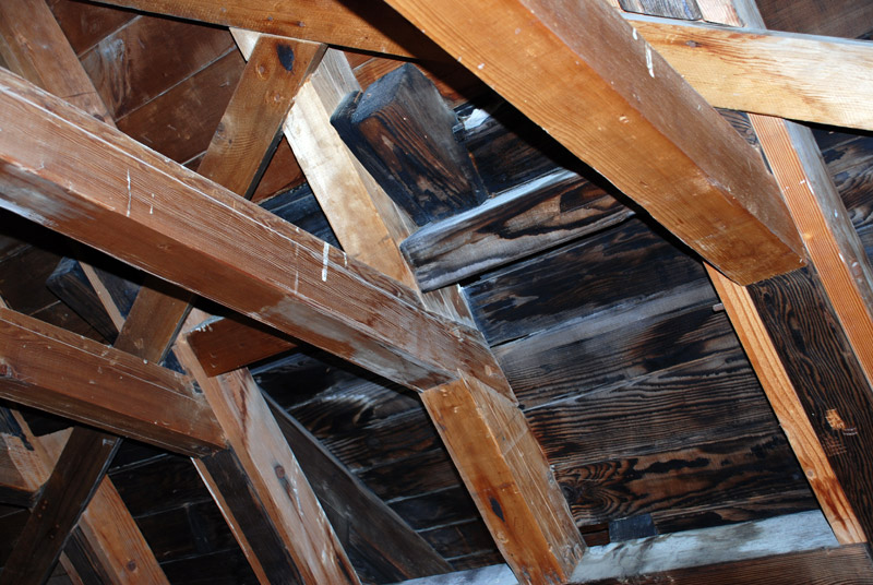
photo of existing attic in 2007 showing scorch marks from original tests. U.S. Army

The furnishings design had been contracted to a New York designer and much of the furnishings were built there. But the sheer number of pieces involved required several other entities, including the RKO prop shop, to create pieces as well with the RKO staff approving the designs and construction materials. Samples of German drapery and bed linens were tested for flammability and similar fabrics were procured.

Once the furnishings were completed and had arrived at the site on May 14, two  RKO staff members supervised the installation based on the interior layout created by the art department. The small rooms were filled to match the congested look of the average German tenement apartment with beds, sofas, cabinets, cribs, table and chairs and the furnishings were completed with the addition of cushions, bed and crib linens and window dressings.
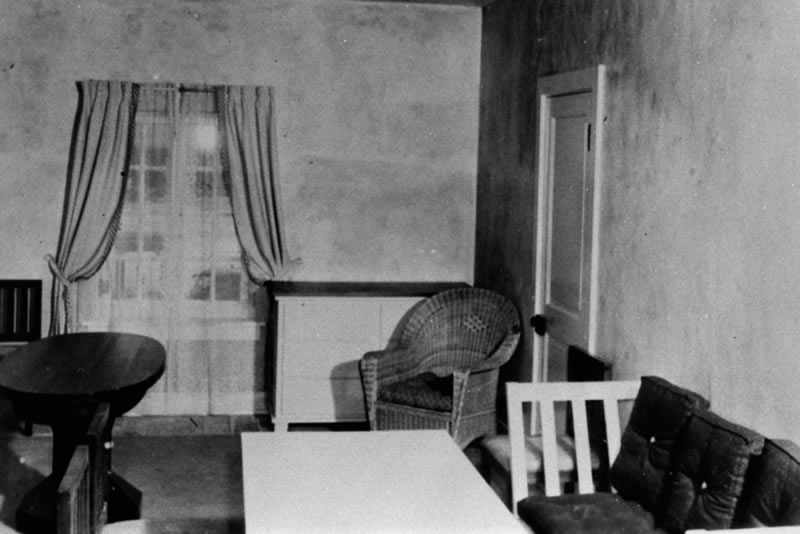
dressed “German” apartment before tests

The black and white photographs taken of the rooms on May 16, 1943, the night before the tests began, look much like set stills that the RKO employees would have taken of hundreds of other sets before. The villages had been completed in 44 days. Bomb tests were begun the next day and were repeated for nearly four months. Each time the structures were quickly repaired and refurnished.
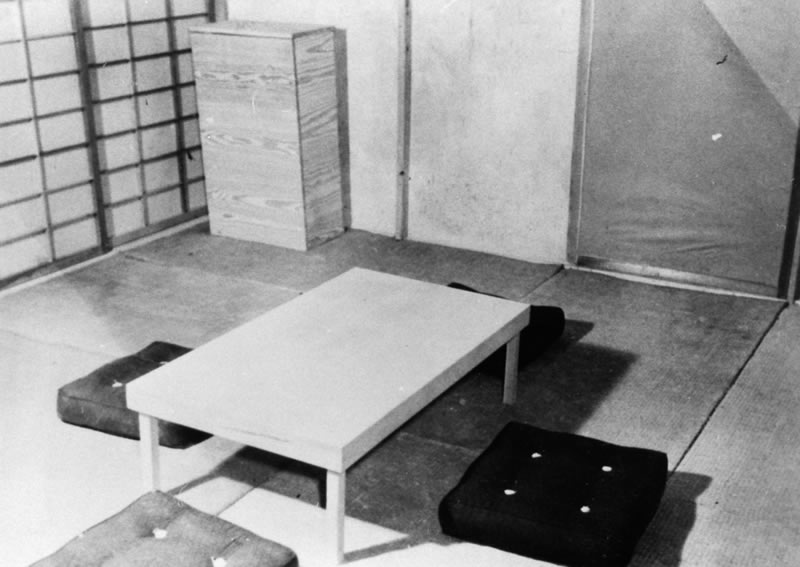
dressed “Japanese” house

Unfortunately there is nothing in the Standard Oil report that names personnel involved with the project.  In the acknowledgement the credit reads – “RKO Studios – Authenticity Division”. So the question is, who were the two individuals from RKO who supervised the final set dressing and who were the other members of the Authenticity Division at RKO?  Several days of research including an afternoon at the Motion Picture Academy library turned up nothing on an ‘RKO Authenticty Division’.
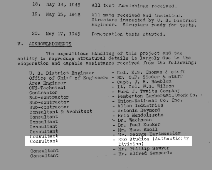
page 16 from Standard Oil Report

What I think most likely happened is that the technical writer who prepared the report, called the studio to find out who to attribute the work to. When he was told the “Art Department”, they most likely assumed the person at the studio was mistaken as the work involved more than artwork, and thus created the title “Authenticity Division” as this more clearly described their contribution. Who exactly those individuals were will probably never be known.
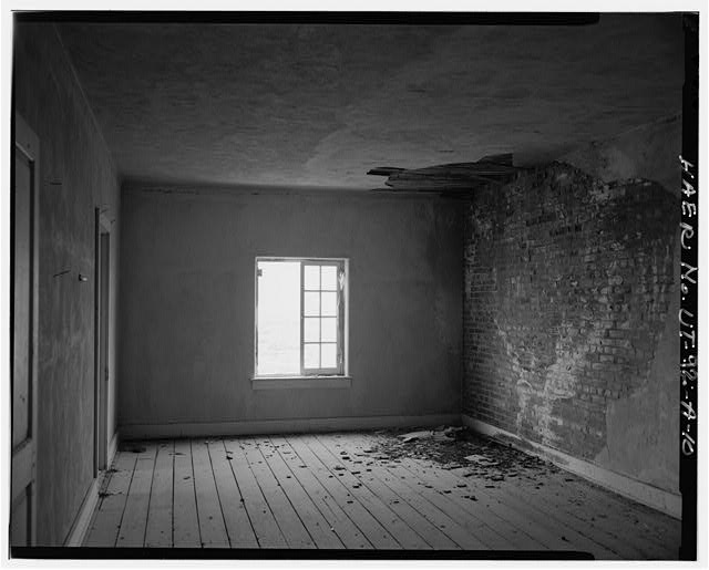
2007 photograph of interior of the existing building – HAER UTAH, 23 DUG, 2A-10

You can learn more about “German Village” at the following site:

http://www.dugway.army.mil/germanvillage/HOME.htm

Sources:

Historical American Engineering Record – HABS/HAER

U.S. Army – Dugway Proving Grounds

Tom Vanderbilt: Survival City – Adventures among the Ruins of Atomic America, New York , Princeton Architectural Press (2002)

Standard Oil Company: Design and Construction of Typical German and Japanese Test Structures at Dugway Proving Grounds, Utah (1943)

Mike Davis: Angriff auf »German Village«, in: Der Spiegel 41/1999

Karen Weitze: HAER No. UT-35-A. und HAER No. UT-92. Historical American Engineering Record, German-Japanese Village (1995)
An article outlining the results of bombing on German cities:

Quick View II Anyone?

I still have a small number of the second model of my Quick View camera angle finders available. This is an updated model with all the common digital sensor sizes as well as the standard film formats for easy cross-reference. I’m debating as to whether or not to order another batch, so I can’t guarantee this won’t be the end of them.

I’m selling these at $50, which is $10 off the normal price.

The Motion Picture

Quote

“The motion picture offers incomparably the greatest field to any creative artist of brush or blueprint today. It is the art of the 20th century and perhaps the greatest art of modern times.”

Production Designer Joseph Urban, 1920

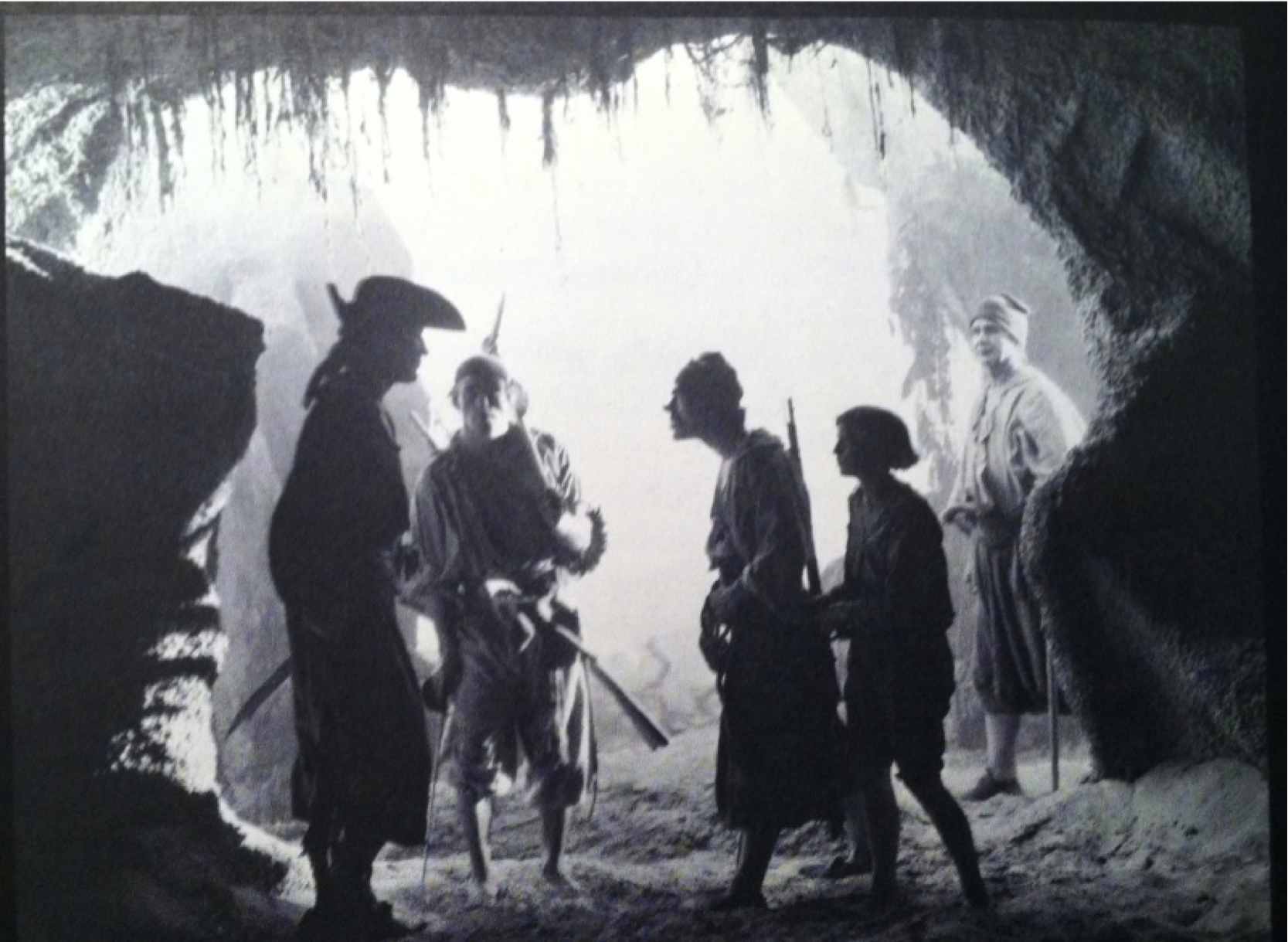
still from Treasure Island, 1920

Hold the Bulldozer! It’s time to dance!

Since what we do is to create things that usually have only a momentary physical life, the ephemeral nature of our profession causes most of us to move back and forth from a state of temporary creative satisfaction to a feeling of complete stupefaction that borders on Nihilism. Take, for example, this satirical short film entitled, “The Life Of A Set Designer”.

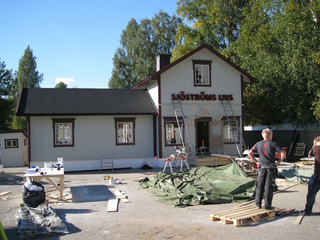
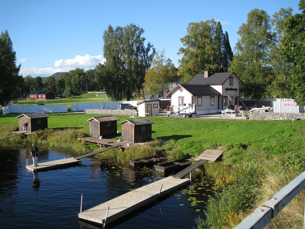
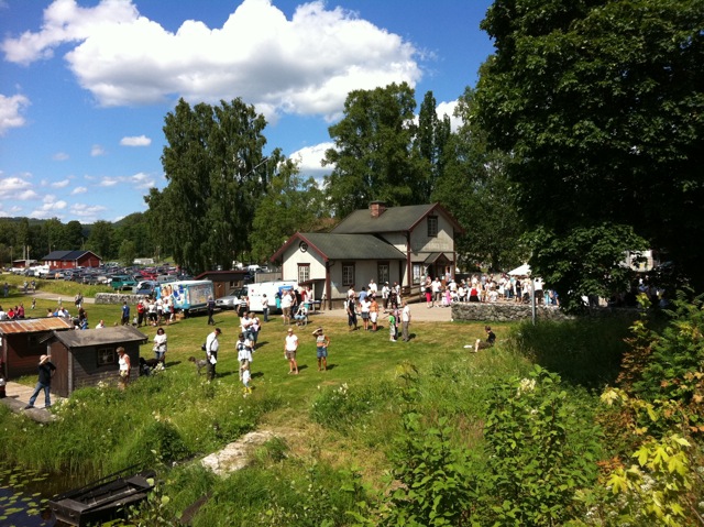
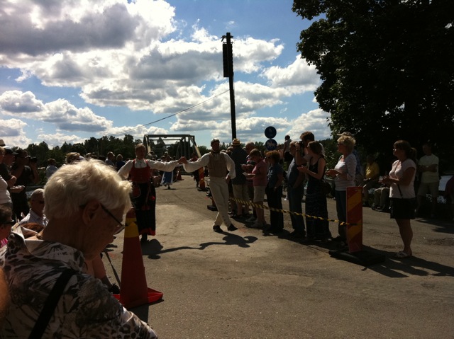
But there are times when those ‘architectural light reflectors’ get a second life, even if only for a short time. Pernilla Olsson, one of our Art Directors in Sweden for “Girl With The Dragon Tattoo”, sent me some photos of one of our sets which has had just such a second life. A small country market set with boathouses that we built in a parking lot was not immediately torn down following filming and the lot owners decided to keep them standing.

This summer it became the site of  “Hälsinge Hambon”, a traditional dance competition famous in Sweden. Here are some shots after completion last year, and in use this summer for the dance competition.

Swedish market set

set after completion in 2010

"Hälsinge Hambon" event 2011


"Hälsinge Hambon" event 2011

Will The Real Ogee Please Stand Up

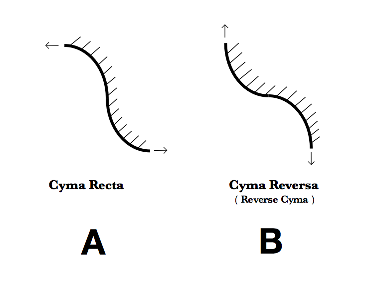
Here’s a simple quiz. Which moulding profile below is an Ogee?

1. A

2. B

3. Both

Correct answer: It depends who you talk to. There are a number of well-respected architectural books which will tell you it’s “A”. They’re wrong, and I’ll explain why.

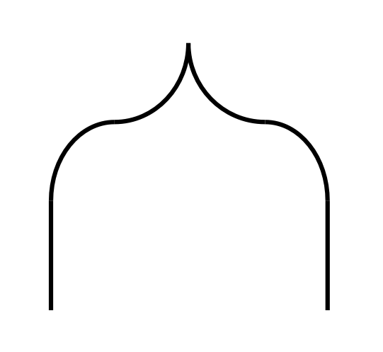
The word Ogee is derived from the medieval French term “Ogyve” (Oh-zheeve), which described a pointed arch as pictured below. The word was Anglicized to “Ogee” and in the late 19th century was shortened to “O.G.”

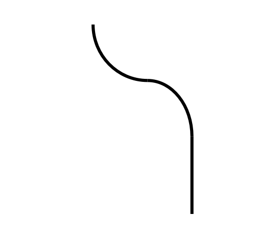
Cut the arch in half and you have a Cyma Reversa, beginning and terminating vertically.

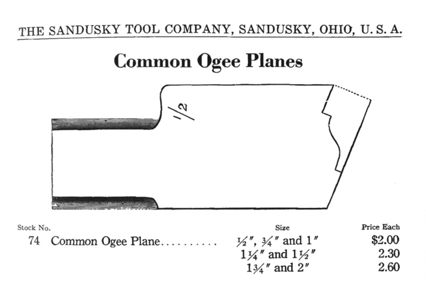
So why the confusion? Well, there wasn’t any in the 18th century. In fact builders and manufacturers of moulding planes were consistent about what constituted an Ogee right into the 20th century. It wasn’t until the late-Victorian academics got involved that things got convoluted, and I think I know why.

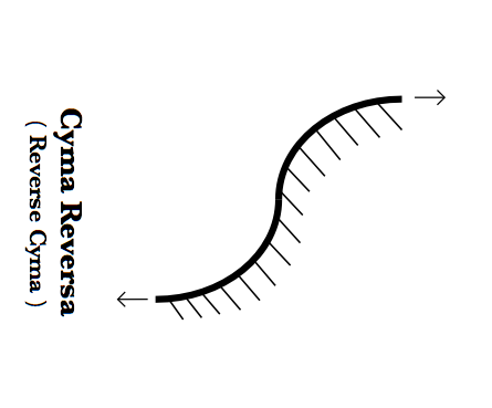
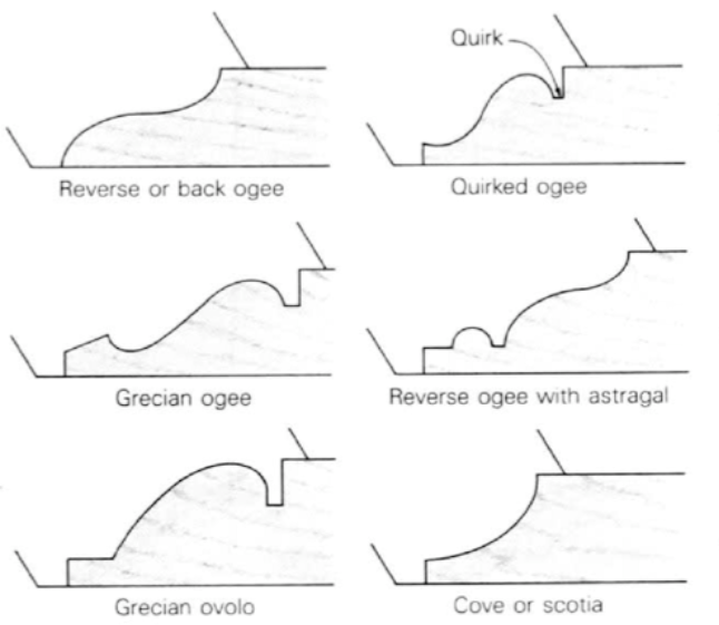
Before the industrial age, wood mouldings were made, or ‘stuck’ by hand with moulding planes. The profiles were cut on their side, like those pictured below. To describe a profile, you need to stand the profile up and read the profiles in descending order. But the people that made mouldings were used to seeing the profiles on their sides, so an ogee, or cyma reversa terminates horizontally when viewed as such.

profiles of complex

Then there’s the terminology. Basically, if a Reverse Cyma is an Ogee, then a Cyma Recta is a Reverse Ogee. At some point I’m sure someone decided, “Gee, that can’t be right. A Reverse Cyma must also be a Reverse Ogee.” Makes sense.

Unfortunately as a wise man once said, “The easiest answers are also usually wrong.” Which in this case is true.

The Historic American Buildings Survey

The Historic American Buildings Survey, or HABS, was established in 1933 by Congress to  create work for unemployed architects and photographers during the Great Depression. Their mission was to document as many representative examples of American architectural structures as possible.

The teams of ‘delineators’ and photographers were hired from all over the country and would document every kind of structure, both public and private. The subjects ranging from well-known structures such as Jefferson’s home, Monticello, to simple barns and gas stations.  They didn’t know that much of what they recorded on vellum and in photos would be the only trace left of these structures as a great many of them were torn down over the preceding years.

In 1969, the Historical American Engineering Record was started as a ‘sister’ agency to record historic engineering and mechanical structures. The HABS / HAER collection, housed and maintained by the Library of Congress, now numbers over 500,000 drawings of 38,000 structures that range from Pre-Columbian ruins to the 20th century. Much of the collection is digitized and is available through the Library of Congress website.

Besides containing a wealth of architectural details, the collection is also a virtual museum of architectural drawing styles. As you look through the collection you can see how the drawing styles of the ‘delineators’ changes as the years pass. The very artistic ‘hand’ of the 1930’s and 40’s gives way to the more spare and graphic styles of the 60’s and 70’s. The collection continues to be added to each year and working on HABS surveys is a right-of-passage for many architectural students.

Below is a beautiful example of a drawing of hardware from 1940. The influence of that period’s drawing style in set design drawings will be obvious to those who have been in the industry since the pre-CAD days.

hardware from the La Rionda Cottage, New Orleans, 1940

Below, a drawing of details from an early Texas home, drawn in 1934.

Texas residence moulding details, 1933

Many of the structures documented were only photographed, but quite a few were documented with drawings as well. A typical survey may include as few as 3 or 4 sheets of drawings. Some contain as many as 20 to 30 sheets of drawings which include moulding and hardware details.

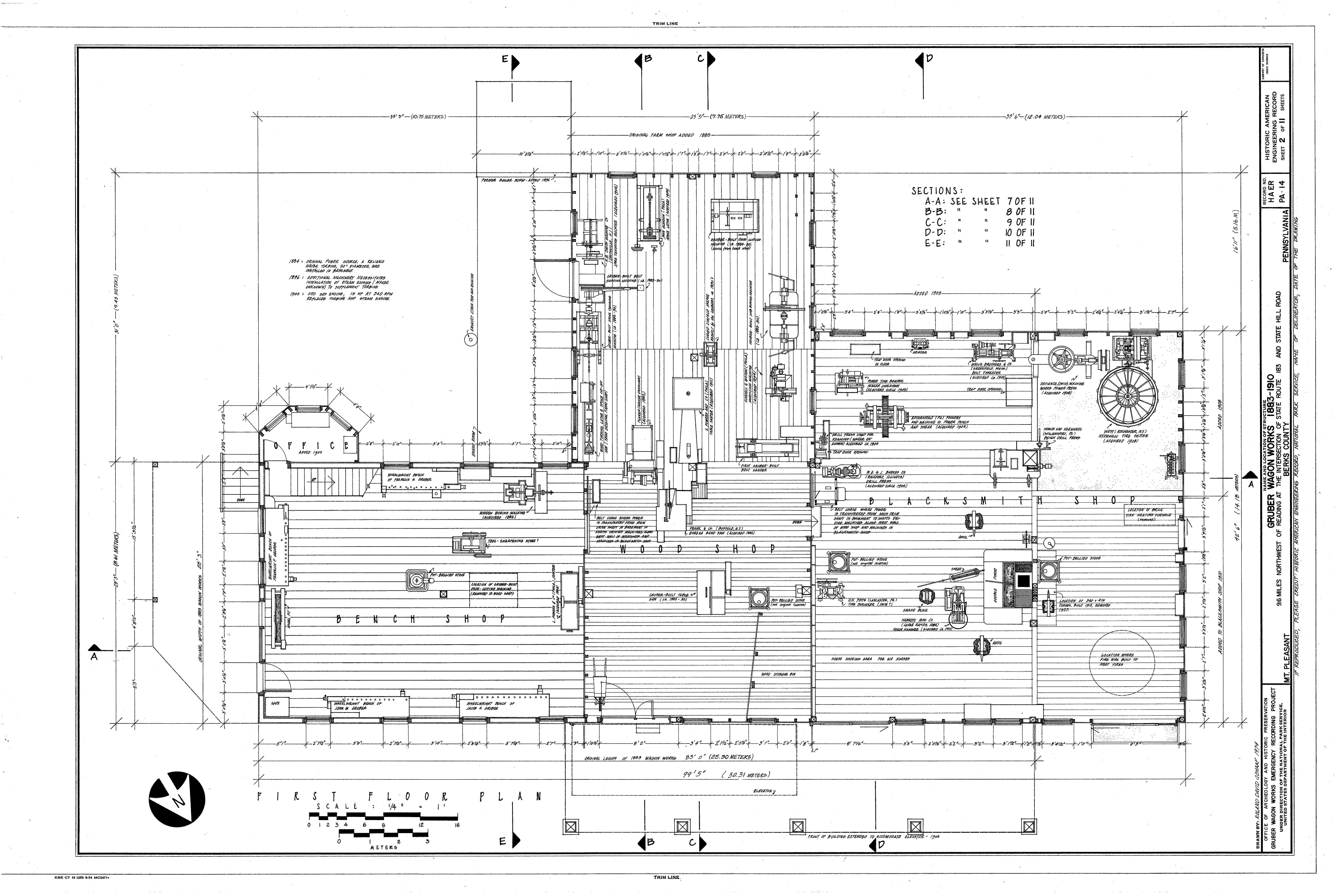
Some, like the 1883 Gruber Wagon Works in Pennsylvania were done as an ’emergency project’, executed when a structure was either in danger of being demolished, or in this case, on the verge of being dismantled and moved to another location. The Blue Marsh Lake Project in the area was the reason for this structure’s relocation.

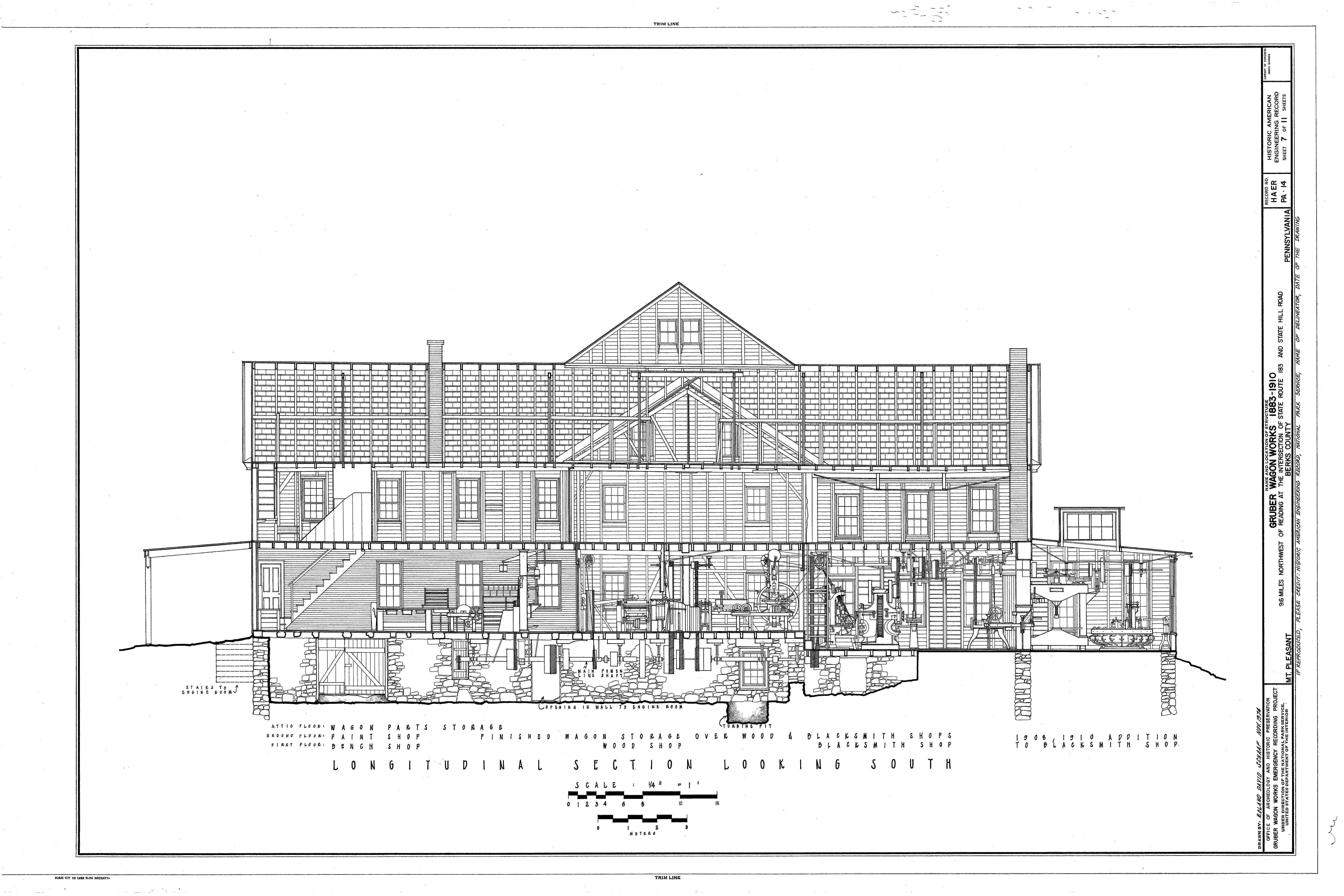
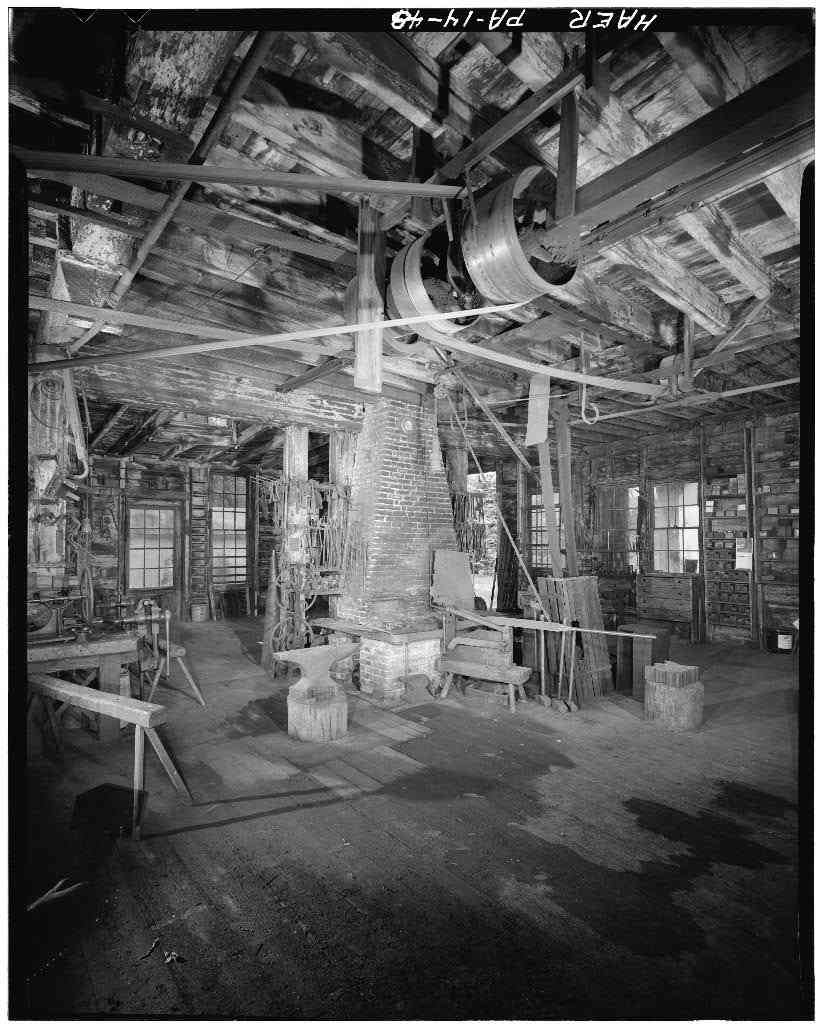
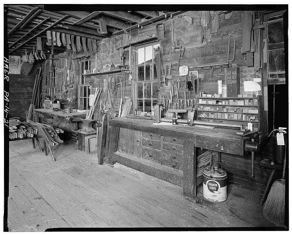
Documented in 1974 by the HAER  in 11 sheets of drawings and 215 photographs, the wagon factory was a rare existing example of late 19th century American industrial age. It contained most of the original belt-driven machinery, still in their original locations.

1974 HAER survey plan of the Gruber Wagon Works


Longitudinal Section

photograph of forge area

photograph of workbench

As a reference and research site for our line of work, it’s pretty hard to equal it. Drawings can be downloaded as a reference tool in either a smaller file size for letter-size copies, or at full resolution for larger prints.

You can search by site name, region, building type or one of a dozen other search terms. But, plan to set aside a fair amount of time when you do a search, as you will quickly find yourself distracted by the huge variety of the material in the collection.

You can find the site at:

http://memory.loc.gov/ammem/collections/habs_haer/index.html

Scandalous Confessions – Part 1

OK, maybe it’s not that scandalous, but if I’d titled the post “Unusual Construction Detail” most of you wouldn’t have bothered to read this.

Anyway, the ‘scandalous’ part is that yesterday I went to tour the Gamble House in Pasadena for the first time ever. Seriously. People who know me and my mania for architectural detail think I’m kidding. It’s always one of those things I’ve meant to do, but because of ‘close-proximity syndrome’ I’ve just never gotten around to it. It was worth the wait.

Yesterday my oldest daughter graduated from the Junior Docent program there and part of their graduation duties was to give their first tour of the house to their parents. So, having my daughter show me around the place was a proud moment. You could say that every inch of the house was designed but that wouldn’t be true. It’s more like every half inch. Photographs do not do it justice.

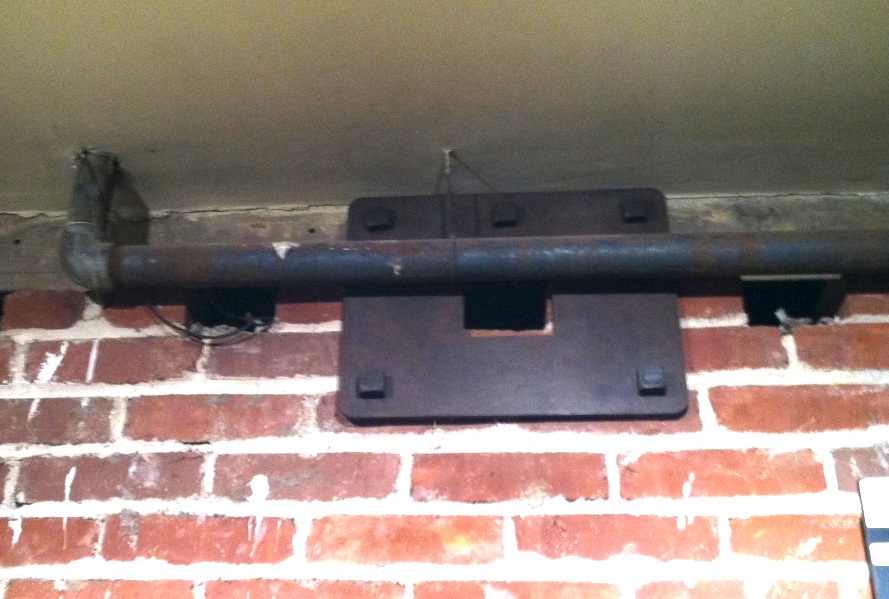
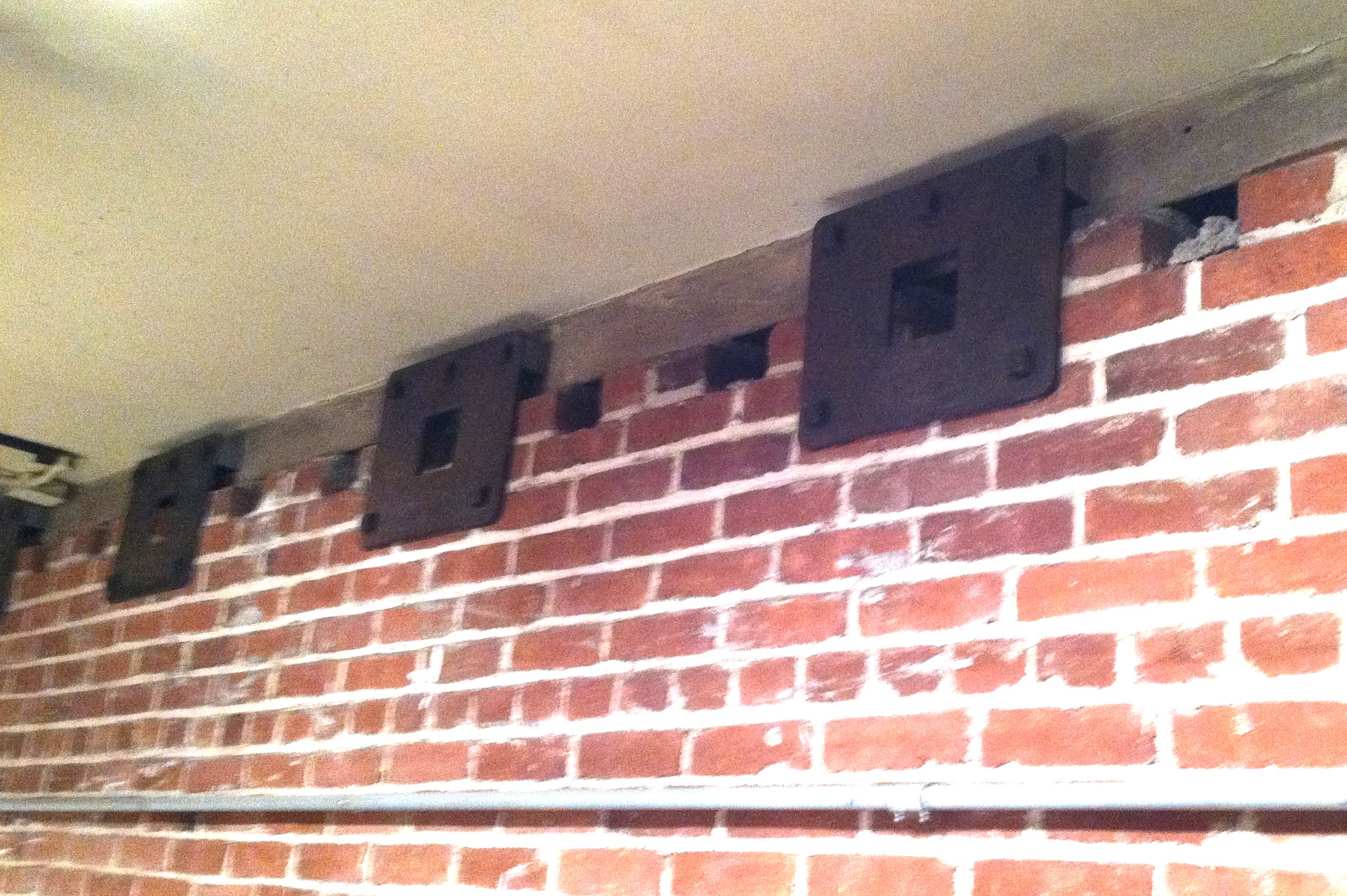
Due to some nasty weather, the ceremony was held in the basement, a place normally off-limits. I looked around at the brick foundation walls of the deep room, surprised to not only find a full basement but a deep one at that. Being that the Gambles were from Ohio I guess It’s not so surprising. I noticed an unusual tie plate that connected the heavy sill joist to the brick and then realized they were spaced fairly closely together all around the foundation.

tie plate in the Gamble House basement

I was assured they were original to the house. Apparently the first question the Gambles put to the architects they interviewed was, “what do you know about earthquakes ?” The 1906 San Francisco earthquake was no doubt fresh in their minds and, being Midwesterners and having no direct experience with quakes, the prospects of even a less damaging quake was terrifying.

The tie plates appear to be about 14″ wide by 12″ tall and are about 3/8″ thick. Each has about a 4″ x 3″ hole punched in the center and is lagged into the brick in two places and the sill joist in three places with what appears to be 3/8″ or 5/16″ bolts. There is a metal spacer between the plate and the joist that is the full width of the plate and is about 1 1/2″ high by 1″ thick. The holes in the plates are aligned with half-brick wide openings in the top of the foundation.

The question in my mind is, were these plates specially designed for the house or were they a readily available item? Considering the Greene’s extreme attention to detail and Henry Greene’s engineering skills, I wouldn’t be surprised that this attention would include parts that few people would ever see. If anyone knows more about it I’d love to hear it.

row of tie plates

Sign Letter Visibility And Focal Length

How big is the moon? Or, more to the point, how does the moon appear to change size so drastically? If you go outside at night and hold a ruler out at arms length, the moon will measure about 3/8″ in diameter. It will fit on the nail of your little finger.

Just as in the photos below, one silhouetting a hawk and the other an 8 foot statue, when shot with a camera it’s apparent size will vary according to the focal length of the lens it’s shot with.

photo by Charlie Riedel AP


Photo by Joseph Rodriguez AP

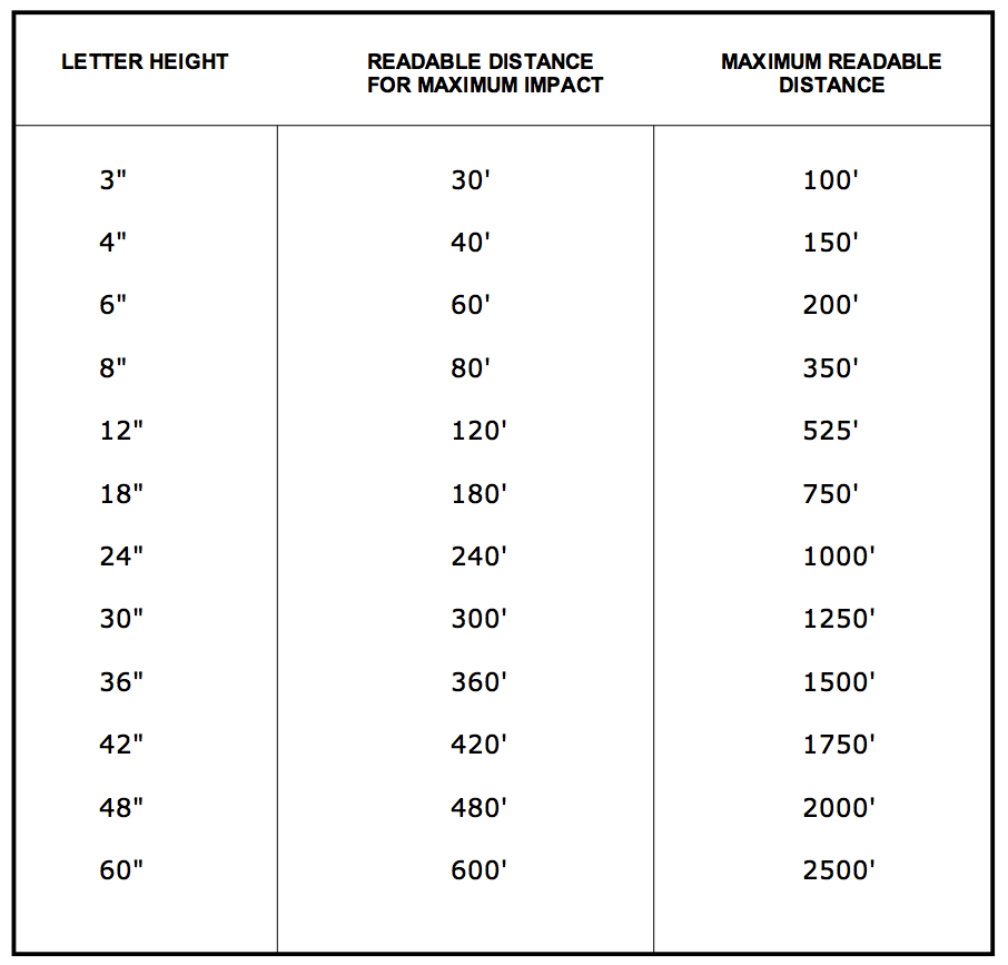
Take sign letters. An Art Director once gave me the chart below which is used to estimate the visibility of letters on signs, depending on the size of the letter and how far the viewer is standing away from it.  Obviously contrast plays a big part here, so this formula works best with red or black letters on a white background. Different colored letters or a darker background can reduce this distance by at least 10%.


These numbers, of course, only hold true when viewing them with the human eye. It’s obviously a different story if you’re shooting with a wide angle or long lens.

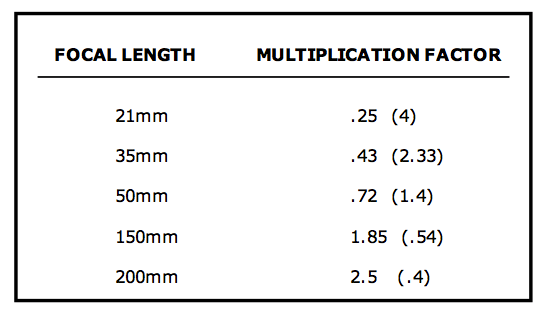
I’ve created a formula for applying the above data depending on the focal length of the lens being used. These focal lengths are equivalent to Super 35 or a 35mm size digital sensor.

To use the chart, just multiply the letter size by the multiplication factor. For instance, if you have a 24″ letter (or object) and shoot it with a 35mm lens, it will appear the same size as a 10.3″ letter would to the naked eye. The number in parenthesis is the division factor.

Please note these are rounded factors and the true result will vary according to the camera and sensor size as well as the lens. To convert the focal length of another sensor size, refer to the previous post on focal length conversion.


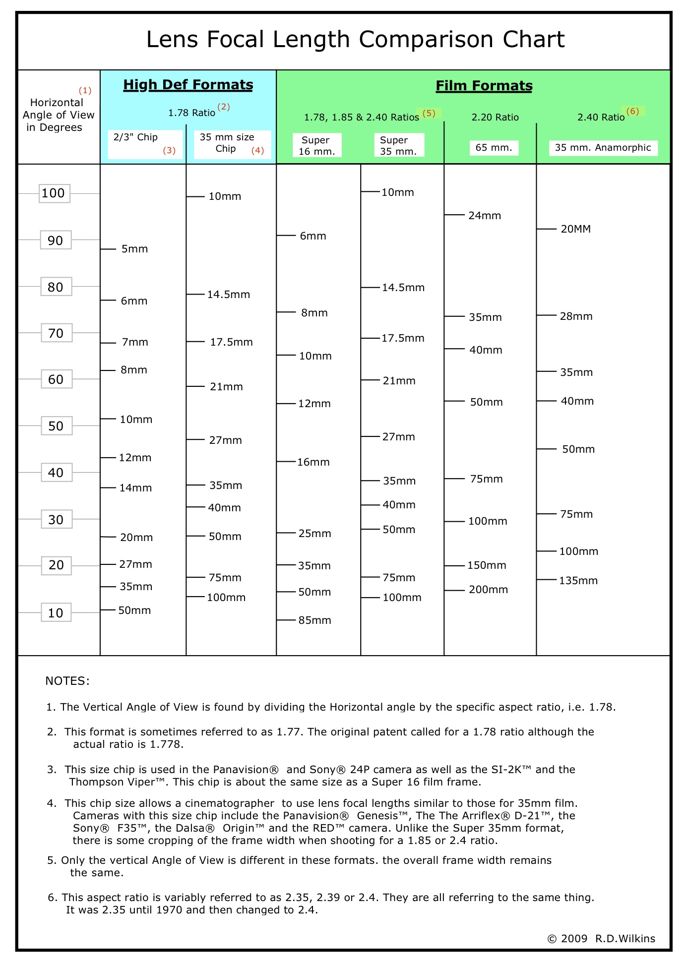
Lens Focal Length Comparison Chart

I created this chart last year for an article in September’s Perspective Magazine. Since then I’ve been asked for it several times and decided I should just post it where it’s easily accessible.

Using a straightedge, his chart will allow you to find the comparable focal lengths of lenses available in many of the popular digital sensor sizes as well as the typical film formats. You can download the PDF by clicking the link below.

Lens Focal Length Comparison Chart

Plus ça change, plus c’est la même chose. . .

It was in the 1920’s that the Art Director first gained a prominent position within the industry. Suddenly directors were forced to consider designed sets that were made to either strongly suggest camera position or to lock one in, as with forced perspective or foreground miniatures.

Men who were trained architects and designers who had been sucked into the studio system had to deal with people who were jealous of this new intruder into the filmmaking process, and did all they could to minimize their influence.

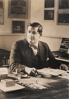
Joseph Urban (1872-1933) was a trained Viennese architect and theatrical designer who had not only designed numerous buildings throughout Europe but was well-respected for his theatrical designs for the Ziegfield Follies. Convinced to come to Hollywood by Randolph Hearst to design a Marion Davies picture, Urban soon found he was unwanted by studio carpenters who were used to building whatever they felt like rather than working from drawings. One carpenter distrusted his designs for a Spanish house and brought in his own reference to copy. Urban had to gently point out that the man’s pictures were actually of a French chateau.

Photo of Joseph Urban

Photoplay Magazine in October of 1920 described a meeting Urban had with one director who described a Buddist Temple that he wanted constructed for a dream sequence.

“You build it right there, about three feet high”, the director told him. “I wheel it up or push it back –  she gets big or she gets small, just as I place the platform; you know what I mean?

“Yes”, murmured Urban, “I know. You want a rubber temple.”

Urban would go on to serve as Art Director, Set Designer and Set Decorator on nearly 30 pictures, as well as simultaneously having a successful architecture career on the East coast.

You can read more about him here:

http://en.wikipedia.org/wiki/Joseph_Urban

http://www.columbia.edu/cu/lweb/eresources/archives/rbml/urban/architectOfDreams/index.html